Thanks for the photos
")
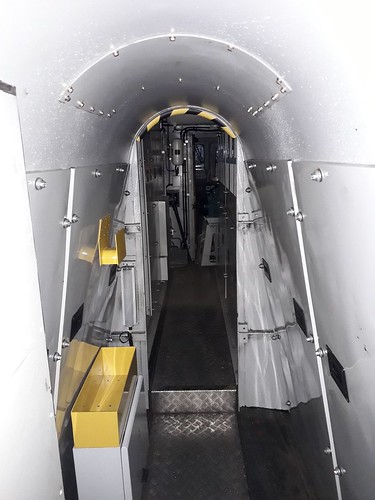
So from top to bottom of the pictures, using educated guesswork to work out some of the anatomy of the loco:
1. Electronically controlled air brake equipment (just behind the cab at the 'electrical' end of the loco, the other end being the 'radiator' end).
2. The end of the traction alternator poking through the partition in the middle (the diesel engine is on the other side of the partition), with a traction inverter and dynamic brake resistor bank on each side. I guess the cylindrical things at roof level are the compressed air reservoirs.
3. Looking from the other side of the partition alongside the engine, the turbochargers are shrouded in a heat protection/fire resistant jacket. Below them are presumably the charge-air coolers, with a fat yellow duct dropping down and along from them carrying the intake air to one bank of cylinders. The traction alternator is not visible, but is low down at that end of the engine.
4. A view a bit further back along the engine, with probably the support tray for the exhaust silencer above it. Not a lot of clearance above the engine, just shows how hard it is to fit all this stuff in a UK size loco. I assume the engine exhaust manifold is down in the 'V' space at the top of the engine, as that seems to be a common layout on big 'V' diesel engines.
Looking at the Cat V16 on the low-loader, I guess most of the pipework on the outside is cooling water plumbing (the water pumps seem to be at the left hand end). On modern engines, 'split' cooling systems seem to be common, so that temperatures in different parts of the engine can be more closely controlled for emission control reasons, hence the plumbing being more complex.
Packaging the equipment inside the new tri-mode class 93 design (for ROG) is going to be fun for the engineers at Stadler...