• Our booking engine at tickets.railforums.co.uk (powered by TrainSplit) helps support the running of the forum with every ticket purchase! Find out more and ask any questions/give us feedback in this thread!

Class 37 throttles

Status
Not open for further replies.

Inversnecky

Member
Joined
1 Jan 2021
Messages
581
Location
Scotland
Hitherto on Train Simulator, I've just driven the Armstrong Powerhouse Class 37, which has a throttle which more or less adds power from initial application (10% plus), but I've been trying out the RETB scenario on the Scottish Western Lines using the supplied 37.

In both the West Highland Line Extension and West Highland Line South, the throttle on the 37/0 and 37/4 acts differently from the AP 37:

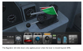
"The Regulator (throttle lever) only applies power when the lever is moved beyond 20%."

"Driving the Class 37/0 The locomotive as modelled has been carefully designed to be driven in the same way as the real thing.... The power handle on this locomotive operates in two stages. In the first part of its travel, the engine is held at idle speed and the torque imposed on it by the generator is controlled proportionately to the handle position. In the second part of its travel, the torque permitted is at the maximum value, and the rotation speed of the engine is controlled by handle position."

Why is there such a variance with the way the AP throttle works? Is one more in tune with the real loco than the other, or was there indeed this sort of variance in subclasses of the real 37s?

Hoping there is someone here who has driven a real 37, who can shed some light on this?
 

Attachments

  • 34955E02-6CE3-4872-894E-A66481030A8B.png
    34955E02-6CE3-4872-894E-A66481030A8B.png
    446.5 KB · Views: 13
Sponsor Post - registered members do not see these adverts; click here to register, or click here to log in
R

RailUK Forums

37057

Member
Joined
3 Jul 2009
Messages
422
I've only been in the seat of a 37/0 a few times on a pres line and even then I can't say I observed it that closely.

Power controller into 'on' is ideal for slow speed shunting movements, to accelerate pull it back accordingly, to cruise push it back accordingly! With any DC motored loco I'd say it's the ammeter you're observing more.

EE 37/0 description...
370.png

BR refurb description...
37.png

AP version is accurate.
 
Last edited:

Inversnecky

Member
Joined
1 Jan 2021
Messages
581
Location
Scotland
Thanks for that. Do I understand correctly from the arrowed bit that that would support the West Highland version?

By ‘engine speed’, is that a reference to the RPM as opposed to locomotive velocity?
 

Attachments

  • 502B112E-194A-497E-A0FE-521E3C53B898.jpeg
    502B112E-194A-497E-A0FE-521E3C53B898.jpeg
    253.7 KB · Views: 7

37057

Member
Joined
3 Jul 2009
Messages
422
Engine speed, but see below for more details.

So for initial rotation of the power controller the generator will be providing traction current to the motors while the engine is in a 'no throttle' state. The engine speed will drop slightly caused by the load placed on the crankshaft by the magnetic forces across the generator. The engine governor detects this and will increase the fuel racks slightly to overcome this. There may be some hunting as the engine governor & generator load regulator 'balance out'. At this point you can imagine a light engine loco gaining momentum slightly while the engine is almost ticking over but it'll sound as if it's a little agitated, this being because it's actually under load and fuelling accordingly. This would be like putting a car in 1st gear and releasing the clutch without pressing the accelerator pedal.

Further rotation of the power handle operates an air operated throttle valve (similar to that in an old bus) that is mechanically linked to the controller. This feeds air to the engine governor throttle cylinder progressively as the controller is pulled back. An analogy of this could be that it works the same as the straight air brake, but air is fed to the engine governor. By doing this the governor is adjusted to open the fuel racks by the driver's command, as engine speed increases the governor operates the generator's load regulator (this is a hydraulic system, operated by a spool valve on the governor) which then increases generator output. The generator then puts further load on the engine and as the governor and load regulator once again fight to find the 'balance' you usually hear and see the loco blurt out a series of 'thrash' as we're accustomed to. As this balances out you then usually hear the turbos pick up and the engine speed remain fairly constant, depending on the type of train it's pulling and the gradient etc.
 
Status
Not open for further replies.

Top