malc-c
Member
- Joined
- 1 Dec 2017
- Messages
- 990
Some may recall that I've done a few rebuilds of my layout over the past few years, the latter was on a 244cm x 60cm board made form 3" x 2" studwork framing with a 9mm MDF top. Well life threw me a few curve balls and the layout didn't progress beyond the track being laid and the platforms being built, and ended up not being used. The studwork started to curl as did the MDF and the plan was to start over again when the opportunity presented itself.
Well, without going into the details, I can now use an area in the main bedroom that I originally set up as a crafting station / desk for the wife. Now the baseboard may just sit on the existing structure, or I may remove the old crafting station and bolt the baseboard to the wall and add supporting legs...
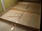
Initially I was going to try and remove the MDF and secure that to a new frame, but then opted to starts again from scratch. Baseboard and frame was constructed from 9mm ply. The initial construction can be seen in the video below
I've not yet finished the board construction as I've waited until I have the servo point motors installed so I can place the cross braces in positions that don't foul the servos. One of the other factors in the slow progress has been an issue with my back which caused me to spend a day in A&E and I'm undergoing treatment for a trapped Femoral nerve, so I can't lean over the layout and working on it can be a short as 20 minutes or if I'm lucky I might go a couple of hours, but often pay for it later on that night ! I've managed to get a bulk of the track relayed (just have to do the straights at the back of the oval), and here is the track plan, with a description of operation which hopefully will keep me entertained for hours when it's finished. I'm still undecided on angling the headshunt H and adding loops behind the backscene to act as a fiddle yard.

Operation
Local Passenger:
DMU – An up stopping DMU will access the bay platform B via crossover A. On departure it can access the down line via the point F. It can continue round as a down stopper that will stop at the station on the mainline. Or placed in the fiddle yard (omitted for clarity) and then run back as an up service via the cross over P.
Freight:
An up freight will access the reception siding C via the crossover A and point F. It will then uncouple and move to the small heads shunt D, and then run round the train via the loop E, and run light engine joining the up line via point F
Yard shunter stabled in the engine shed G makes its way to the reception siding C and collects the uncoupled brake van. It reverses into head shunt H until the brake van is over point M. It then deposits the brake van in the departure siding N
It then reverses until its over point M and then moves forward into the reception siding C and couples to what was the last wagon at the rear of the rake. It reverses into head shunt H. It then pushes the wagons into sidings K via point O, uncoupling as required to split the train in two, with half the train being shunted into the goods depot J
When empty the wagons are taken from the goods yard and placed in the siding L. The shunter then collects the remaining half of the train form siding K and moves them into the goods depot. Once they have been emptied the shunter drags them towards head shunt H until the last wagon is clear of point Q. It then pushes the wagons into siding L to couple to the empties form the first half. It then pulls all the wagons into headshunt H. Once clear of point O it then pushes the wagons into the departure siding N and couples the waiting brake van to the end of the train. The shunter uncouples from the train and moves back to the headshunt H. The train of empties is now ready for a light engine movement to come and collect them
Coal:
An up coal will access the reception siding C via the crossover A and point F. It will then uncouple and move to the small heads shunt D, and then run round the train via the loop E, and run light engine joining the up line via point F
Yard shunter stabled in the engine shed G makes its way to the reception siding C and collects the uncoupled brake van. It reverses into head shunt H until the brake van is over point M. It then deposits the brake van in the departure siding N
It then makes its way into headshunt D via the loop E, then reverses into the reception siding C and couples onto the coal train. It then pushes the wagons into siding I to be unloaded into the coal staves. It can then be uncoupled and stationed back into the engine shed.
Once empty, the shunter couple back onto the wagons and pulls them into the reception siding C, then uncouples and runs round the train via head shunt B and loop E and then couples to what will now be the first wagon in the train.
The shunter now pulls into head shunt H until the last wagon is clear of point M. It then pushes the wagons into the departure siding N where it couples to the waiting brake van. The shunter uncouples form the wagons and goes back towards headshunt H to leave point M clear so a light loco movement can come and collect the train from the departure siding N.
This was the stage the layout was in last night. I have since completed all the sidings - and suffering for it -but no pain no gain as the saying goes.
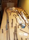
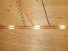
And after an afternoons work, the track is down
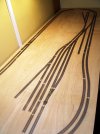
Still need to apply some more pins in places, and fit the sleepers under the joints, but on the whole quite pleased with how it looks. Now i know where the points are I can make up and fit the cross bracing and then move on to adding dropper wires and hook up the DCC bus.
Well, without going into the details, I can now use an area in the main bedroom that I originally set up as a crafting station / desk for the wife. Now the baseboard may just sit on the existing structure, or I may remove the old crafting station and bolt the baseboard to the wall and add supporting legs...
Initially I was going to try and remove the MDF and secure that to a new frame, but then opted to starts again from scratch. Baseboard and frame was constructed from 9mm ply. The initial construction can be seen in the video below
I've not yet finished the board construction as I've waited until I have the servo point motors installed so I can place the cross braces in positions that don't foul the servos. One of the other factors in the slow progress has been an issue with my back which caused me to spend a day in A&E and I'm undergoing treatment for a trapped Femoral nerve, so I can't lean over the layout and working on it can be a short as 20 minutes or if I'm lucky I might go a couple of hours, but often pay for it later on that night ! I've managed to get a bulk of the track relayed (just have to do the straights at the back of the oval), and here is the track plan, with a description of operation which hopefully will keep me entertained for hours when it's finished. I'm still undecided on angling the headshunt H and adding loops behind the backscene to act as a fiddle yard.

Operation
Local Passenger:
DMU – An up stopping DMU will access the bay platform B via crossover A. On departure it can access the down line via the point F. It can continue round as a down stopper that will stop at the station on the mainline. Or placed in the fiddle yard (omitted for clarity) and then run back as an up service via the cross over P.
Freight:
An up freight will access the reception siding C via the crossover A and point F. It will then uncouple and move to the small heads shunt D, and then run round the train via the loop E, and run light engine joining the up line via point F
Yard shunter stabled in the engine shed G makes its way to the reception siding C and collects the uncoupled brake van. It reverses into head shunt H until the brake van is over point M. It then deposits the brake van in the departure siding N
It then reverses until its over point M and then moves forward into the reception siding C and couples to what was the last wagon at the rear of the rake. It reverses into head shunt H. It then pushes the wagons into sidings K via point O, uncoupling as required to split the train in two, with half the train being shunted into the goods depot J
When empty the wagons are taken from the goods yard and placed in the siding L. The shunter then collects the remaining half of the train form siding K and moves them into the goods depot. Once they have been emptied the shunter drags them towards head shunt H until the last wagon is clear of point Q. It then pushes the wagons into siding L to couple to the empties form the first half. It then pulls all the wagons into headshunt H. Once clear of point O it then pushes the wagons into the departure siding N and couples the waiting brake van to the end of the train. The shunter uncouples from the train and moves back to the headshunt H. The train of empties is now ready for a light engine movement to come and collect them
Coal:
An up coal will access the reception siding C via the crossover A and point F. It will then uncouple and move to the small heads shunt D, and then run round the train via the loop E, and run light engine joining the up line via point F
Yard shunter stabled in the engine shed G makes its way to the reception siding C and collects the uncoupled brake van. It reverses into head shunt H until the brake van is over point M. It then deposits the brake van in the departure siding N
It then makes its way into headshunt D via the loop E, then reverses into the reception siding C and couples onto the coal train. It then pushes the wagons into siding I to be unloaded into the coal staves. It can then be uncoupled and stationed back into the engine shed.
Once empty, the shunter couple back onto the wagons and pulls them into the reception siding C, then uncouples and runs round the train via head shunt B and loop E and then couples to what will now be the first wagon in the train.
The shunter now pulls into head shunt H until the last wagon is clear of point M. It then pushes the wagons into the departure siding N where it couples to the waiting brake van. The shunter uncouples form the wagons and goes back towards headshunt H to leave point M clear so a light loco movement can come and collect the train from the departure siding N.
This was the stage the layout was in last night. I have since completed all the sidings - and suffering for it -but no pain no gain as the saying goes.

And after an afternoons work, the track is down

Still need to apply some more pins in places, and fit the sleepers under the joints, but on the whole quite pleased with how it looks. Now i know where the points are I can make up and fit the cross bracing and then move on to adding dropper wires and hook up the DCC bus.
Last edited:


