• Our booking engine at tickets.railforums.co.uk (powered by TrainSplit) helps support the running of the forum with every ticket purchase! Find out more and ask any questions/give us feedback in this thread!

Converting points : Electrofrog < > Insulfrog

Status
Not open for further replies.

Justin Smith

Member
Joined
14 Nov 2009
Messages
1,059
Location
Sheffield
Non DCC !

Am I right that an Insulfrog point can be used to isolate a section of track and "park" a loco (whilst a different one is operated), whereas an Electrofrog point lets current through on the unswitched line ?

If so is there way of converting Electrofrog points to Insulfrog ?
And vice verse ?

Also, using a meter, how can you tell if a point is Insulfrog or Eelctrofrog ?
 
Sponsor Post - registered members do not see these adverts; click here to register, or click here to log in
R

RailUK Forums

malc-c

Member
Joined
1 Dec 2017
Messages
990
You can visually see the difference between Electrofrog and Insulfrog points as the tip of the frog is plastic in an insulfrog point, so no need to use a meter.

Yes, in a DC system Insulfrog points "switch" the power to the route selected, so if you have two sidings or passing loop for example, a loco could run in to one siding or the loop, points are changed to the main line (or other siding) and another train can run pass (or enter the other siding) without effecting the first loco. You don't need to do any additional wiring or use isolated sections as the point does the isolation.

AFAIK you can't convert an electrofrog point to insulfrog as the frog is formed by the two rails which touch making both rails live, hence the need for insulated joiners on both inner rails to avoid a short. You may be able to hack the links under the point, and do away with the connection wire to the frog thus isolating it, but may experience running issues as a result. The use of said insulated joiners effectively isolate the point form both tracks, so you will need to use feeds to the tracks (ideally via switches, if you want to then isolate that section). The frog of an Electrofrog point needs to be connected to the track feed via a change over switch attached to the point motor to maintain correct polarity and enable smooth running with short wheelbase locos such as 0-6-0 shunters.
 

Cowley

Forum Staff
Staff Member
Global Moderator
Joined
15 Apr 2016
Messages
15,771
Location
Devon
A comprehensive reply by @malc-c there.
I just took photos of one of each type in my fiddle yard and this is an Electrofrog:
5E2513C7-4472-45F6-892C-D1D3EB648287.jpeg

And this is the Insulfrog (you can see the plastic frog that Malc is talking about):
D0120DBA-9155-49EE-BD91-B4EEABE80551.jpeg

My railway is DCC so the whole thing is live and there’s no need to add the switches in for the polarity. I just have the two previously mentioned isolating fishplates here:
7BFC0ABE-9867-494A-8CC3-669262D2E9B4.jpeg
 

Justin Smith

Member
Joined
14 Nov 2009
Messages
1,059
Location
Sheffield
Thanks Malc & Cowley
I have been doing some experiments, and it could be the points are faulty I suppose, but in the picture below :

1 - Is not isolated (it was tested out of the circuit), yet it appears to have an insulating section of plastic on the frog.
2 - Does not appear to be isolated, note the "X" drawn on the layout base
3 - Does appear to be isolated, yet looks exactly the same as 2 !
4 - Is not isolated (it was tested out of circuit), yet, again, it looks exactly the same as 2 !

Isolated (Insulfrog) and non isolated (Electrofrog) points 800W L20.jpg

I am thinking of using switches and isolating rail joiners, how well do the latter work, as in keeping the track in perfect alignment ? Are they as good as full metal ones ?
Again, I was shocked when I saw the price of Peco isolating switches (put "model railway" on it and double or treble the price...), I was thinking of buying a load of these. I reckon I can insert them into the layout base. Would they do the job ? And do you have to break the circuit on both rails or will one rail be enough (e.g. if one has a loop with opposite hand point each end) ?
 

cadder toad

Member
Joined
2 May 2015
Messages
97
These all look like insulfrog points to me. Are you able to check for continuity? With a meter or continuity tester(light bulb)? Plenty on you tube to explain the differences between insulfrog and electrofrog. Try this - not necessarily the best on but simply the first one -there's no pic of an electrofrog point for example.


Its better not to rely on fish plates for alignment (these days I see they're referred to as 'rail joiners'). Get the track in the right position particularly level - no dips -and the crosslevels - no twists. The plastic fishplates will align track but won't hold it in position as well as a metal fishplate - but shouldn't need to if the track is laid properly.

Insulfrog are simpler to wire but more prone to trains stalling if the track isn't level. More pick ups always helps - for diesels with pick ups on both bogies then I wouldn't expect stalling on an insulfrog point. An 0-6-0 shunter might be different.

The switches you asked about look ok but a bit pricey. What do they mean by latched? What you need is a single pole double throw (SPDT). They're not needed with either insulfrog or electrofrog points as the blades do the switching. Sometimes the contacts on the blades need adjusting to achieve this.
 

malc-c

Member
Joined
1 Dec 2017
Messages
990
To my untrained eye, 1 is insulfrog, even though they use a metal triangle as the frog, there appears to be a gap with plastic between it and the two inner of the point. 2 is what we know as a standard insulfrog with the isolation be made by the plastic point to the frog, as does images 3 and 4. If you look at the images above in Cowley's post, the frog and the check rails are all metal on the electrofrog point.

Regarding the plastic fishplates / joiners are typically only fitted to the two short rails that form the frog, with standard metal joiners on the two outer running rails. There are tones of websites covering the wiring of both types of points so no real point in repeating things here, but loops, passing loops, and crossings are all covered.

As for switches - there is no real need to buy expensive on/off switches. Small miniature toggle switches can handle the small currents a loco would typically draw at 12v. You can get 25 small switches form Amazon for less than £10 here which are ideal for isolating DC sections of track, or to operate point motors etc

@cadder toad I'm guessing that the termed "latched" is the same as "locking" in the link I provided. Meaning that they stay in the position they are thrown, ie a normal SPDT switch, compared to those that are sprung loaded and return to a central off position after being pressed and released.
 

Justin Smith

Member
Joined
14 Nov 2009
Messages
1,059
Location
Sheffield
To my untrained eye, 1 is insulfrog, even though they use a metal triangle as the frog, there appears to be a gap with plastic between it and the two inner of the point. 2 is what we know as a standard insulfrog with the isolation be made by the plastic point to the frog, as does images 3 and 4. If you look at the images above in Cowley's post, the frog and the check rails are all metal on the electrofrog point.
I get what you are saying about the points appear to be insulfrog, yet they do not isolate the non running line (other than number 3), 1 and 4 for certain as they were tested out of the circuit, i.e. no chance of current creeping round "the other way".
Basically I do not understand it !
I am concluding I will have to go for separate current switches and insulated rail joiners.
 

malc-c

Member
Joined
1 Dec 2017
Messages
990
So you are saying that if you set the DMV to continuity and place the probes across rails A & B you get continuity between them on all points other than #3?

Isolated (Insulfrog) and non isolated (Electrofrog) points 800W L20.jpg

Also, using a meter, how can you tell if a point is Insulfrog or Eelctrofrog ?

As above, just set the meter to continuity (most beep when shorting the two probes) and place them across rails A and B as shown. If the meter sounds a beep, or changed from OL to 0.00 then the frog is electrically connected and will be classed as elecrofrog. If there is no conductivity then it's an Insulfrog
 
Last edited:

Justin Smith

Member
Joined
14 Nov 2009
Messages
1,059
Location
Sheffield
As for switches - there is no real need to buy expensive on/off switches. Small miniature toggle switches can handle the small currents a loco would typically draw at 12v. You can get 25 small switches form Amazon for less than £10 here which are ideal for isolating DC sections of track, or to operate point motors etc
I have ordered some of those switches and also some insulated rail joiners.
I'm assuming because there is only one pole that only one track needs to be isolated ?
 

cadder toad

Member
Joined
2 May 2015
Messages
97
Generally need two insulating fishplates on each point. The common of the switch connects to the frog and the switch is used to direct either +ve or -ve to the frog.
This short video should explains electrofrogs with pictures.
I'm sure the Peco booklet on electrofrog wiring would be useful but the web page says its not in stock. Some possibly useful diagrams here too(not a video)
 

malc-c

Member
Joined
1 Dec 2017
Messages
990
If you are using insulfrog points the route selected is the one that get energised as the point does the switching of the power, thus, in the case of a set of sidings or bay platform, the point can be set to one route, the loco can enter the siding (or bay platform) and once fully passed the point can isolated by moving the point to the straight position rather then the branch.

peco_insulfrog_wiring.jpg


If you use electrofrog with the same setup, as insulated joiners are fitted to either just the inner rails that go to the frog, or all four rails that form the branch or main tracks. the tracks the point is connected to is always dead so separate power feeds are required to them.

peco_electrofrog_wiring.jpg

If the feed to the bay or siding is via a switch the the loco is totally isolated.

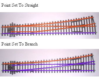
As you will see in the lower image the two inner rails of an elecrofrog point become the same polarity as the frog joins them together, hence the need for insulation joints as they will otherwise cause a direct short. Most electrofrog points have a frog wire that connects to the centre pin of a single pole double through (SPDT) switch. Power is then connected to the outer two pins of the switch. When the switch is in one position the positive feed is connected to the centre pin and thus the frog. Changing the switch to the other position connects the negative feed. Most point motors have this switching option so the polarity is changed as the point is changed automatically.

The switches can also be used to isolate sections of sidings or the ends of terminus lines, so for example the loco that brought the train in can be isolated so another loco can be attached at the other end and take the train back out. Here the switch is used to bridge the connection (although using the switch as mentioned above still works)

Isolating%20Section.gif


In the above the SPDT switch can be used, with the power from the rail or the feed going to the centre pin, and the wire to the track that is being isolated connected to either outer pin

There is a lot of information on track electrics, either DC or DCC on the internet. This site https://www.pls-layouts.co.uk/html/frog_types.htm is very helpful and was where the diagrams above were found.

Hope that helps
 

Justin Smith

Member
Joined
14 Nov 2009
Messages
1,059
Location
Sheffield
Thanks for that everyone.
As I said I have ordered the switches, along with a few curved Peco points which I believe are insulfrog and therefore may not need the switches, but I will see once they are fitted because for some reason (esp when actually installed on the site) some points which are insulfroog do not seem to isolate the particular section. Maybe it's because it's a loop with a LH point one end and a RH the other so the two insulfrog each isolate a different polarity each end and it just gets through the other ? ? Just thinking out loud !
 

malc-c

Member
Joined
1 Dec 2017
Messages
990
If you use insulfrog points for a passing loop then switching both points to the loop isolates the main straight and vice versa. Have one set to the loop and the other set to main and both tracks are powered, at least up to the opposing point.
 

Justin Smith

Member
Joined
14 Nov 2009
Messages
1,059
Location
Sheffield
Thanks for that everyone.
As I said I have ordered the switches, along with a few curved Peco points which I believe are insulfrog and therefore may not need the switches, but I will see once they are fitted because for some reason (esp when actually installed on the site) some points which are insulfrog do not seem to isolate the particular section. Maybe it's because it's a loop with a LH point one end and a RH the other so the two insulfrog each isolate a different polarity each end and it just gets through the other ? Just thinking out loud !
I have just discovered this is correct. Despite having two insulfrog points the current gets through on the "always live" rail which is different at each end of the loop ! NOTE : it is not just a straight forward loop off a line and back on to it, it is a loop from a siding back to a main line
Thus I am now getting into the delights of isolating track sections...... I bought some insulated rail joiners but they don't do what I want really, so I have ordered some isolating track sections. Unfortunately though they do not have terminals on them (even at £5 each ! ) so I will probably have to solder the wires onto the fishplates at each end..... For the afore mentioned loop I only needed one to break the current at one end, so long as it was the track which was "always live" at the same end.
Interestingly (and I think this is right) I have another loop which has non isolating point at both ends but that will still only need two isolating sections, so long as I put them on the same rail !
 
Last edited:

Justin Smith

Member
Joined
14 Nov 2009
Messages
1,059
Location
Sheffield
I have spent days installing a reverse loop (within the centre loop), so a train going in one way comes out going the other. However, it puts a dead short on the 12V line ! If I'd thought about it, bearing in mind what I said in the above post, it was possible that would happen......
What I need is an isolator section of track but with the break on both lines. I can then link both to a double pole switch (in case of poor supply through the tracks one way) and that should sort it. Though what would happen when a loco goes over it ? Can one get a both tracks isolator ? Or has anyone any other ideas ? Unfortunately both points are non isolated, and one cannot easily be changed because it is a curved point with a tighter radius than the Peco ones.
 
Status
Not open for further replies.

Top