robintw
Member
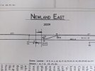
I've been looking at a diagram of Newland East signal box (between Malvern and Worcester), the central part of the diagram showing the crossover is attached.
I can't see any Facing Point Locks on the diagram for this crossover. Does that mean they weren't provided? Am I correct that FPLs would have to be provided for passenger trains to use the crossover in the facing direction, and if they weren't provided then they'd need clipping? This diagram is from 2009, and although I don't believe there are any timetabled trains using the crossover, I believe it is used in times of disruption.
If they were there, how would FPLs usually be shown on the diagram? Would it just be another number next to the points on the diagram?
(For context, the reason I'm asking this is that my wife made a birthday cake for me with the levers of Newland East signal box on it, as it was my local box growing up. She only had a diagram and no colour photo of the box, so she tried to work out the colours of each lever by determining their function from the diagram. She accidentally made 13 and 15 blue, as FPLs, whereas actually they're shunt signals - but that made me wonder where the FPLs actually are...).
Thanks,
Robin