• Our booking engine at tickets.railforums.co.uk (powered by TrainSplit) helps support the running of the forum with every ticket purchase! Find out more and ask any questions/give us feedback in this thread!

MML Electrification: progress updates

59CosG95

Established Member
Joined
18 Aug 2013
Messages
6,489
Location
Between Peterborough & Bedlington
Not quite, it could be best described as a 125mph capable OLE system; attainable with subtle modifications.

The OLE on the MML was one (if not) the first installation of auto-tensioned Mk3B in the UK. The system has the correct contact and catenary wire tensions (11kN/11kN) and does not need re-tensioning if single pantographs of the HSP or HSX type are used. Its issue is that where STC's are in situ these the steady arms are of the shallow curve type, and not the deep curve type predominantly seen on headspans. The shallow curve type (when fitted to STCs) provide insufficient uplift for anything greater than 110mph; these would be an issue around the Ampthill Tunnel area where the HST speed is 125mph on both the Down and Up Fast Lines as alluded to elsewhere in this thread. There are also several other issues on the MML:

- Bridge grading and clearances at fitted overbridges, it is assume that these were setup for no more than 100mph when installed - records are unclear!
- Clearance from the contact wire to the lowest spanwire, which is substandard in certain headspan areas
- Presence of split span wires between the Fast Lines and Slow Lines - a case in point is around Stewartby
- A general drift away from the correct heights and staggers for anything more than 100mph.

The ECML uses STC's with drop brackets and deep curve steady arms. When correctly setup these can accommodate >125mph operation and have 250mm - 300mm uplift - whereas the shallow curve type only give something like 150mm.

West of Stockley Viaduct Series 1 is installed, this can be operated at up to 140mph with the correct pantograph types, but not where any overbridges use the fitted GFRP bridge arms - these are limited to 125mph to avoid forming hard spots in the contact wire.

Yes the tensions should be fine provided nice new modern pantographs are used.

South of Bedford probably Long Meadow Farm (Sundon) - Bedford South (where UKMS125 commences) would require 125mph EMU operation, it's been done between Paddington and Stockley Junction before so it would just require modification (and money £££ from the project team). The other areas which could potentially be done are Elstree & Borehamwood - St Albans (or even further south at Mill Hill if you want to resolve the Fast line tunnel aerodynamics issue at Elstree.), St Albans to Harpenden (HST 115mph/120mph spilt), and then finally Luton - Sundon.

The biggest time gain - aka BCR - is Luton/Sundon - Bedford.

Harpenden - Luton is quite a quick win (although it varies from 110mph down to 90mph); there is only one fitted bridge to worry about regrading. The linespeed also never exceeds 110mph (it's mainly 105mph or 100mph on the Fast Lines) so little if any modifications to the STC's, required around the Chiltern Green and Luton Airport Parkway areas, would be needed.
I've included these very useful comments from @WiredUp taken from the EMR 360 thread. This should hopefully explain the work south of Bedford.
 
Sponsor Post - registered members do not see these adverts; click here to register, or click here to log in
R

RailUK Forums

edwin_m

Veteran Member
Joined
21 Apr 2013
Messages
24,884
Location
Nottingham
Our 2 new aircraft carriers are supposed to have cost over £6bn. How many aircraft carrier cost equivalents to electrify to Sheffield and Nottingham? Justifying these massive spending projects often seems to swing on job creation and retention factors.
So test and trace could have bought us about 13 more aircraft carriers, or at least a third of HS2, or I don't know how many potholes.

The RIA cost challenge said the recent MML electrification was about £1.8m per single track km (stk), which I presume excludes re-building the slow lines over Sharbrook. So somewhere in the region of £300m to get to Sheffield (based on a guess of the track-km). So probably the bow portion of an aircraft carrier for this scheme, or test and trace would probably have paid for the whole network...
 

Dr Hoo

Established Member
Joined
10 Nov 2015
Messages
3,957
Location
Hope Valley
So test and trace could have bought us about 13 more aircraft carriers, or at least a third of HS2, or I don't know how many potholes.

The RIA cost challenge said the recent MML electrification was about £1.8m per single track km (stk), which I presume excludes re-building the slow lines over Sharbrook. So somewhere in the region of £300m to get to Sheffield (based on a guess of the track-km). So probably the bow portion of an aircraft carrier for this scheme, or test and trace would probably have paid for the whole network...
But Network Rail have just announced that they've spend £1.5 billion on the Bedford-Corby bit. And what most of us would see as the 'first phase' isn't even finished yet with Braybrooke/Market Harborough and sorting out the stuff south of Bedford for 125mph running still to do.

Without getting too bogged down with stk and route miles (which have multiple tracks) and recognising that there is a lot of re-modelling necessary at Leicester and around Sheffield in particular there is no way that it will be done with £300 million. And that won't cover the obvious diversionary routes, won't enable electric haulage of freight and still leave the majority of passenger services at Nottingham, Derby and Sheffield diesel operated anyway.

The current railway is just awesomely expensive to upgrade. :'(
 

ohgoditsjames

Member
Joined
16 Jun 2019
Messages
379
Location
Sheffield & Shipley
From the local rag in Sheffield

It comes ahead of the Integrated Rail Plan which - at best - could give the green light to the eastern leg of HS2, Northern Powerhouse Rail and the electrification of Midland Mainline to Sheffield. It could be published as early as next week.​

Gavin Crook, of Network Rail, said electrification was a big part of moves to decarbonise the railways and they were ‘actively’ working on a plan to electrify the Midland Mainline. Sheffield is the largest city and busiest station not on the electrified network.​


OxtedL

Established Member
Associate Staff
Quizmaster
Joined
23 Mar 2011
Messages
2,570
But Network Rail have just announced that they've spend £1.5 billion on the Bedford-Corby bit.
The £1.5 billion quoted will include things like the £200m Derby remodelling. It's a price tag for a much bigger programme of things than just the electrification.
 

swt_passenger

Veteran Member
Joined
7 Apr 2010
Messages
31,385
The £1.5 billion quoted will include things like the £200m Derby remodelling. It's a price tag for a much bigger programme of things than just the electrification.
Not the first time NR have scored such an own goal. (Without searching they quoted a vastly wrong figure a few months ago for something big on the ECML.).

The PR department seem to think including a much higher cost than necessary is a good thing.
 

Bald Rick

Veteran Member
Joined
28 Sep 2010
Messages
29,176
The RIA cost challenge said the recent MML electrification was about £1.8m per single track km (stk

Thats just the cost of the OLE, power and distribution works. It doesn’t include signalling (which should be relatively little for the MML) and route clearance (which will be a lot). You can easily double that number.

I forget the exact number, but Harboro’ to Sheffield and Nottingham is about 400stk. That excludes the Erewash valley, extending beyond Sheffield / Nottingham, nor any of the branches, but does include all tracks / loops on multi-track sections and the Trent East curve.

won't enable electric haulage of freight

The Mountsorrel - Elstree / Radlett flow could go over. Every little helps!
 

WiredUp

Member
Joined
17 May 2021
Messages
87
Location
Bedford
Thats just the cost of the OLE, power and distribution works. It doesn’t include signalling (which should be relatively little for the MML) and route clearance (which will be a lot). You can easily double that number.

I forget the exact number, but Harboro’ to Sheffield and Nottingham is about 400stk. That excludes the Erewash valley, extending beyond Sheffield / Nottingham, nor any of the branches, but does include all tracks / loops on multi-track sections and the Trent East curve.


The Mountsorrel - Elstree / Radlett flow could go over. Every little helps!
Absolutely - it leaves off immunisation and any works in stations/bridges etc. to achieve clearances (as you mention), rerouting of services/cable troughing (particularly for low level ATF in stations), track remodelling, relocation of E&P assets, and the little things oft-forgotten like new signage at access points and the like!

It all adds up....
 

Bald Rick

Veteran Member
Joined
28 Sep 2010
Messages
29,176
Absolutely - it leaves off immunisation and any works in stations/bridges etc. to achieve clearances (as you mention), rerouting of services/cable troughing (particularly for low level ATF in stations), track remodelling, relocation of E&P assets, and the little things oft-forgotten like new signage at access points and the like!

It all adds up....

Certainly does. Although IIRC all the resignalling done at Derby and Trent is electrification friendly, as was Leicester when it was resignalled in, err, 1985 (?)


Nice to think so but both those services seem to be booked via Manton!

(Sorry, BR.) :)

Cunning Plan fails again!
 

59CosG95

Established Member
Joined
18 Aug 2013
Messages
6,489
Location
Between Peterborough & Bedlington
MML Wiring Progressometer 49.0 (Updated as of 26th of May 2021)
Mileages are from St. Pancras. Unless mentioned otherwise, all reference to the "Fast" side refers to tracks on the western side of the "10-foot" (centre of the track pairs), and the "Slow" side for the tracks on the eastern side.
Foundations, steelwork, catenary & contact complete. Sectioning Arrangements now in a separate list.


South of Bedford
  • 16 new structures have been erected to replace headspans between Cricklewood & the North Circular; these are confirmed to be part of the works for the new Brent Cross West station.
  • Until the OLE on the Fasts is upgraded for 125mph multi-pan running, the Class 810s will be restricted to diesel-only south of Bedford.


Bedford (49m 65ch) - Wellingborough (65m 09ch); LIVE
  • Wires through Bedford on the Down Fast (P4) are now complete. Additionally, the existing wires on Platforms 2 & 3 are now extended to Tensorex portal SPC2/80/599, replacing the former Balance Weights north of the island platform. All roads wired from Bedford to Wellingborough.


Wellingborough (65m 09ch) - Kettering (72m 01ch); LIVE
  • Work to return the 4th platform (P4) at Wellingborough to public use is now complete. The Up Slow between Kettering & Sharnbrook is now in full use.
  • All lines are now wired within Wellingborough station. These continue along all lines to Kettering.
  • North of Wellingborough, the Down Goods Loop (west of the Down Fast) and the Arrival/Departure Line (adjacent to the now-in-service Up Slow) are now wired, along with the westernmost siding in Wellingborough Up Yard. There doesn't seem to be any concrete plan to put northern access into the yard yet, though.


Kettering (72m 01ch) - Glendon Jct (74m 00ch) - Corby (79m 40ch); LIVE
  • All 4 lines are now wired through Kettering station. On the Fasts, wires finish at Tensorex portal SPC3/116/654 (also the live limit on the Fasts; 72m 40ch), while those on the Slows continue to Glendon Jct & Corby, and thence to the limits of wiring.
    Limits of Wiring:
    • Down Corby: GSM1/127/641.
    • Up Corby: GSM1/128/317.
    • Corby Reception Line: GSM1/128/478. (79m 68ch)
  • Between SPC3/116/654 and Kettering North Jn, around 30 or so TTCs are in place on the Fasts; the vast majority now have Booms. A visual survey by yours truly from Linear Park (north of the A43 and east of the MML) shows that pretty much everything is in between the A43 (O/B 47E) & Hipwell Rd (O/B 47), except for one structure between SPC3/119/392/UF & SPC3/119/513/DF. By KNJ RRAP, a lone pile, presumably for the missing structure, awaits installation. On most of these structures already installed, Earth Wire brackets have now appeared.
  • At Glendon, the new Kettering North TSC (AT-feeding capable) has been connected to the OLE on the Corby lines. Spanwires for the Main lines are coiled up O.O.U. until wires head to Market Harborough. Of the 3 TTCs south of the overlap & north of the overbridge, the northernmost one (SPC3/119/731/DF) is in and boomed, the central one (SPC3/119/671/DF) is in and boomed, and the southernmost one (SPC3/119/611/DF) is in and boomed.
  • Both TTCs over the Fasts in the overlap have now been installed, boomed and EW-bracketed.


Glendon Jct (74m 00ch) - Market Harborough (82m 74ch) - part of Key Output 1A
  • Braybrooke Substation (ATFS) approved. To be located here: (https://goo.gl/maps/fuy1uZeDjdQ2).
  • Enabling Works happened; the land has now been returned to its original state (possibly to keep land in original condition?). Civils & Electrical Design contract awarded. To be completed "Autumn 2022".
  • The extent of wiring towards Market Harborough has now been as good as confirmed to reach the station. Approval has been given for final design work to be carried out on that section of route. De-vegetation work in the Braybrooke area has been carried out. No signs of work in the Rushton or Desboro' areas yet, but the Up Fast cess just north of Kettering North Jn (in the Glendon area) has recently had saplings removed.
  • Ground Investigation Works are taking/have taken place between Kettering & Great Bowden (north of Market Harborough); this implies Great Bowden will be the northern limit of wiring until further wiring gets authorised.


The Future - Midlands Engine Rail (Midlands Connect), MMLU Key Output 2 & HS2
  • Electrification proposed from Market Harborough to Leicester, Loughborough, Nottingham & Derby; as part of the Midlands Connect strategy. The March 2020 Budget committed to the scheme; details were alleged to be found in the July Spending Review. When this will actually be released (what with COVID-19) remains to be seen.
  • Electrification proposed from Clay Cross HS2 Connection to Sheffield (Midland) as part of HS2 works.
  • Currently, no electrification is proposed between Clay Cross HS2 Connection & Nottingham, or Tupton & Derby (via Belper).


    Any updates would be greatly appreciated.
 
Last edited:

InTheEastMids

Member
Joined
31 Jan 2016
Messages
727
  • Braybrooke Substation (ATFS) approved. To be located here: ([URL]https://goo.gl/maps/fuy1uZeDjdQ2[/URL]).
  • Enabling Works happened; the land has now been returned to its original state (possibly to keep land in original condition?). Civils & Electrical Design contract awarded. To be completed "Autumn 2022".
  • The extent of wiring towards Market Harborough has now been as good as confirmed to reach the station. Approval has been given for final design work to be carried out on that section of route. De-vegetation work in the Braybrooke area has been carried out. No signs of work in the Rushton or Desboro' areas yet, but the Up Fast cess just north of Kettering North Jn (in the Glendon area) has recently had saplings removed.
  • Ground Investigation Works are taking/have taken place between Kettering & Great Bowden (north of Market Harborough); this implies Great Bowden will be the northern limit of wiring until further wiring gets authorised.
Thanks as ever for the update.

Contractor is now on site for Braybrooke substation - there's a gatehouse at the top of Kettering Road, adjacent to the A6 junction, and it looks like the route for the site access road from the entrance to the substation site has been cleared.

Deveg work has been carried out all the way into Market Harborough - particularly noticeable between the Scotland Road and Kettering Road bridges, and will continue up to 83m, 572y which is probably the Northern limit of electrification for now.
 

GRALISTAIR

Established Member
Joined
11 Apr 2012
Messages
7,875
Location
Dalton GA USA & Preston Lancs
Thanks as ever for the update.

Contractor is now on site for Braybrooke substation - there's a gatehouse at the top of Kettering Road, adjacent to the A6 junction, and it looks like the route for the site access road from the entrance to the substation site has been cleared.

Deveg work has been carried out all the way into Market Harborough - particularly noticeable between the Scotland Road and Kettering Road bridges, and will continue up to 83m, 572y which is probably the Northern limit of electrification for now.
Fantastic- lets hope someone posts some photos.
 

SouthEastBuses

On Moderation
Joined
15 Nov 2019
Messages
1,800
Location
uk
With the fact that the MML electrification south of Bedford is only capable of max speeds of 160 km/h (100 mph), I have a question:

Will the MML electrification south of Bedford will be replaced with Alstom CLevers and Furrey+Frey Series 1s (the models used north of Bedford)?
Or keep the current Mk3s, but do some minor modifications (like increasing mm uplift or something like that) to resemble like those on the ECML and WCML northern section, so that they can be 200 km/h (125 mph) capable?
 

Flying Phil

Established Member
Joined
18 Apr 2016
Messages
1,928
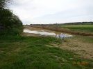
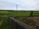
I was able to see over the work to the South of Mkt Harborough. There is a new access route to the sub station site as "IntheEastMids" says. It is through or alongside the new construction site for lots of new houses etc between the old A6 and railway line. The new route runs alongside the MML for a short distance.
The actual substation site is still untouched (- apart from some small flags!)
I have some pictures..... but also IT woes tonight!DSC00630.JPGDSC00635.JPGDSC00632.JPG
 
Last edited:

59CosG95

Established Member
Joined
18 Aug 2013
Messages
6,489
Location
Between Peterborough & Bedlington
I was able to see over the work to the South of Mkt Harborough. There is a new access route to the sub station site as "IntheEastMids" says. It is through or alongside the new construction site for lots of new houses etc between the old A6 and railway line. The new route runs alongside the MML for a short distance.
The actual substation site is still untouched (- apart from some small flags!)
I have some pictures..... but also IT woes tonight!View attachment 97183View attachment 97184View attachment 97187
Thanks very much for these @Flying Phil - the demarcation of the "CDM Area" in the second picture looks world-beating :lol:

How likely is it that the NG substation & 25-0-25 feeder will be on the same site? If it runs alongside the MML at the actual site (à la Welwyn) then I'd say likely, but if it doesn't (à la Borehamwood ATFS, which feeds from Elstree 400kV sub) then probably not.
 

swt_passenger

Veteran Member
Joined
7 Apr 2010
Messages
31,385
Thanks very much for these @Flying Phil - the demarcation of the "CDM Area" in the second picture looks world-beating :lol:

How likely is it that the NG substation & 25-0-25 feeder will be on the same site? If it runs alongside the MML at the actual site (à la Welwyn) then I'd say likely, but if it doesn't (à la Borehamwood ATFS, which feeds from Elstree 400kV sub) then probably not.
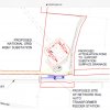
Everything surrounds that single pylon, the planning application, (if I can find it again), has a quite detailed layout of all the components. It looks like the trackside equipment might be squeezed in between this site and the railway, but I suppose NR will have a separate application for that, which I haven’t found yet.

Kettering planning, Application KET/2017/0791

By the way, when we were discussing the area of such a finished grid site a few weeks ago, (ie 1.5 football pitches), it sits within quite a massive underground earthing mat, this would not be visible afterwards, but presumably removes the possibility of normal agricultural use.
 

Attachments

  • PDD-32519-LAY-028Rev4.LP.0791.2017.KET.211217.pdf
    1.3 MB · Views: 81
Last edited:

swt_passenger

Veteran Member
Joined
7 Apr 2010
Messages
31,385
Do all feeder stations have those?
I think this is more to do with the grid side than railway, but I expect there’s all sorts of site specific earthing when 25 kV is flying around. (I’ve found a decent location drawing now, which I’ll add to the earlier post.)
 

Nottingham59

Established Member
Joined
10 Dec 2019
Messages
1,640
Location
Nottingham
decent location drawing now, which I’ll add to the earlier post.
Thanks for posting that.

Looks like they're taking a tap off all three phases on each side of the 400kV, but only using two on each side. I assume the output is two 25-0-25 feeders to the adjacent NR lineside installation?
 

swt_passenger

Veteran Member
Joined
7 Apr 2010
Messages
31,385
Thanks for posting that.

Looks like they're taking a tap off all three phases on each side of the 400kV, but only using two on each side. I assume the output is two 25-0-25 feeders to the adjacent NR lineside installation?
I would assume so, but I’d also await an expert‘s view. But the design and access statement definitely says it’s a 400kV > 25kV stepdown, from two independent grid circuits, with the outputs to the NR compound being underground.
 
Last edited:

Flying Phil

Established Member
Joined
18 Apr 2016
Messages
1,928
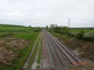
This is the view to the South from the overbridge - This will be the site of the NR equipment.
DSC00633.JPG
 

swt_passenger

Veteran Member
Joined
7 Apr 2010
Messages
31,385
This is the view to the South from the overbridge - This will be the site of the NR equipment.
That bridge will be well placed to monitor progress @Flying Phil - should be quite interesting to see how they modify the pylon, (to add the extended arms for the drops into the transformer compound). I assume that’s why they apparently need such a long planning lead time for the Grid work, in order to turn off the two 400 kV circuits, while maintaining all supplies elsewhere.
 

Nottingham59

Established Member
Joined
10 Dec 2019
Messages
1,640
Location
Nottingham
This will be the site of the NR equipment
That will be to the left of the track, in this photo, AIUI. Let's hope they set it back a bit from the track edge so they don't occupy space that could be used in future for a freight passing loop at that location.
 

swt_passenger

Veteran Member
Joined
7 Apr 2010
Messages
31,385
That will be to the left of the track, in this photo, AIUI. Let's hope they set it back a bit from the track edge so they don't occupy space that could be used in future for a freight passing loop at that location.
I think that’s highly unlikely for space reasons, given where the ATFS is shown in planning drawings. (Eg pdf in #4278)

But if such a loop were to be positioned passing the ATFS, and electrified, it would add unnecessary complexity to the associated neutral section and the overhead track feeding connections, normally switches allow for isolations in either direction, or temporary changes to the normal set up of the two grid supplies.

I think they’d normally avoid having a loop there, unless there really was nowhere else to put it.
 

mr_jrt

Established Member
Joined
30 May 2011
Messages
1,407
Location
Brighton
Rather than just a loop forevermore, presumably one day in the distant far off future you would want to extend that loop as part of a four tracking scheme.... :)
 

WAO

Member
Joined
10 Mar 2019
Messages
663
The planning drawing, (#4278) only show the NG 400kV substation (or GSP) which includes the 400/25 SGT's in its ownership. The tower affected (ZA216) shows all three phases being brought down with all being used, a different pair for each transformer. The red line denotes the limit of the NG compound; the NR ATFS will be outside of this in a separate NR compound and is not shown. For comparison see the Patford Bridge site air view, with the NR kit squeezed in below.

If the wires were not going North to Leicester etc, this NG substation could have been built on a much smaller and cheaper scale.

WAO
 

Nottingham59

Established Member
Joined
10 Dec 2019
Messages
1,640
Location
Nottingham
given where the ATFS is shown in planning drawings
Yes, I know. That's why I mention it. There are acres of open fields all around, yet NR is choosing to locate the ATFS exactly where it will get in the way of any future network expansion. I know it's unlikely in this case, but it does seem to me they've missing the opportunity for nil-cost future-proofing here.

I think they’d normally avoid having a loop there, unless there really was nowhere else to put it.
It just happens to be along a section of track where the trackbed is particularly wide, and I assume there was a loop or a 4-track section in the past. Hence the space for the access road alongside the existing tracks.

(EDIT: In fact the 6inch OS map from 1950 shows there was a passing loop at this exact spot running from near Market Harborough all the way to Desborough.
https://maps.nls.uk/view/101593329
1622550059945.png
 

Attachments

  • 1622548806366.png
    1622548806366.png
    9.8 KB · Views: 13
Last edited:

swt_passenger

Veteran Member
Joined
7 Apr 2010
Messages
31,385
The planning drawing, (#4278) only show the NG 400kV substation (or GSP) which includes the 400/25 SGT's in its ownership. The tower affected (ZA216) shows all three phases being brought down with all being used, a different pair for each transformer. The red line denotes the limit of the NG compound; the NR ATFS will be outside of this in a separate NR compound and is not shown. For comparison see the Patford Bridge site air view, with the NR kit squeezed in below.

If the wires were not going North to Leicester etc, this NG substation could have been built on a much smaller and cheaper scale.

WAO
The design and access statement for the planning application does define the NR compound position as being the blue coloured equipment lineside between the grid compound and the track, it’s shown in grey in my earlier attachment:
 

Attachments

  • AEC6BCE5-7D29-446F-B5BD-27684029BB2F.jpeg
    AEC6BCE5-7D29-446F-B5BD-27684029BB2F.jpeg
    580.6 KB · Views: 74
Last edited:

Top