• Our booking engine at tickets.railforums.co.uk (powered by TrainSplit) helps support the running of the forum with every ticket purchase! Find out more and ask any questions/give us feedback in this thread!

MML Electrification: progress updates

AM9

Veteran Member
Joined
13 May 2014
Messages
14,235
Location
St Albans
In the current standards the real killer is that the default gap is sized not to transmit lightening to structures (+ allowance for upward movement etc.) rather than just the rail supply voltage.
If you mean lightning as in discharges during storms, then the difference between a 750V DC tramway conductor and a 25kV (or even 50 kV) OLE system is lost in the noise of an 100MV cloud strike. As far as local flashovers are concerned, a 1500VDC OLE (when they existed here) for a given traffic density, would have a far higher current capability, liable to cause more damage and lifting of local earth potentials than a 25kV ac OLE which although rated for a longer section, assumes a current about 3% of the equivalent DC demand per train in section. On that basis, the clearance for voltage protection alone would still only need to be less than 50mm*, (witness the deployment of 6.25kV ac on established 1500VDC on the GE suburban lines in the '60s. The rest of the clearance as you say would be the kinetic envelope of live parts.
* for 41kV max peak voltages
 
Sponsor Post - registered members do not see these adverts; click here to register, or click here to log in
R

RailUK Forums

Elecman

Established Member
Joined
31 Dec 2013
Messages
2,893
Location
Lancashire
In the current standards the real killer is that the default gap is sized not to transmit lightning to structures (+ allowance for upward movement etc.) rather than just the rail supply voltage.
Hence the new use of surge arrestors on low clearance structures to overcome the voltage surge from a nearby lightning strike
 

Kneedown

Established Member
Joined
29 Dec 2007
Messages
1,768
Location
Nottinghamshire
Whilst walking to Kettering depot last Weds, I noticed in the adjacent Network Rail yard some STC cantilevers and associated registration arms stored there.
I know the insulators used to be ceramic, and thought that was still the case. On giving one of them a gentle "test wiggle" however, It was apparent that they were made of flexible, silicone rubber type material.
I wonder what the longevity of this material is, compared to regular ceramic?
 

59CosG95

Established Member
Joined
18 Aug 2013
Messages
6,488
Location
Between Peterborough & Bedlington
Whilst walking to Kettering depot last Weds, I noticed in the adjacent Network Rail yard some STC cantilevers and associated registration arms stored there.
I know the insulators used to be ceramic, and thought that was still the case. On giving one of them a gentle "test wiggle" however, It was apparent that they were made of flexible, silicone rubber type material.
I wonder what the longevity of this material is, compared to regular ceramic?
I'm not too sure on the longevity side of things, but the silicone rubber insulators have been in vogue since the early/mid '90s as they don't suffer the same 'explosive fractures' that the ceramic ones do.

Said fractures are normally caused by water ingress (followed by freeze-thaw expansion) or being struck with an air rifle pellet (or another kind of thrown/shot object), accidentally or otherwise. Dropping one also causes it to shatter. (This has resulted in permanent eye damage in the past)

Silicone rubber ones don't shatter when you drop them!
 

AM9

Veteran Member
Joined
13 May 2014
Messages
14,235
Location
St Albans
I'm not too sure on the longevity side of things, but the silicone rubber insulators have been in vogue since the early/mid '90s as they don't suffer the same 'explosive fractures' that the ceramic ones do.

Said fractures are normally caused by water ingress (followed by freeze-thaw expansion) or being struck with an air rifle pellet (or another kind of thrown/shot object), accidentally or otherwise. Dropping one also causes it to shatter. (This has resulted in permanent eye damage in the past)

Silicone rubber ones don't shatter when you drop them!
That's really interesting. As an anecdote, waynackin the early '70s I used to commute from Colchester to Ilford. One morning, whilst watching the 06:42 approaching platform 3, the leading pantograph got tangled in the knitting, bringing the whole lot down. After a delay of about an hour all trains were rerouted via platform 1 & 2. We stood waiting on that island platform amongst many pieces of insulator and a couple of almost complete ones. They were glazed and broken pieces had razor sharp edges. Had that happened in the evening peak, when that platform would have been quite crowded, I dread to think of what the consequences might have been.
 

Kneedown

Established Member
Joined
29 Dec 2007
Messages
1,768
Location
Nottinghamshire
Said fractures are normally caused by water ingress (followed by freeze-thaw expansion)
I can relate to that. Exactly the reason 109's transformer went flash "BANG" when I put the pan up on it last year. My trainee at the time still quickens his pace when walking past one!
 

GRALISTAIR

Established Member
Joined
11 Apr 2012
Messages
7,862
Location
Dalton GA USA & Preston Lancs
The biggest weaknesses of any ceramic material is fracture toughness. They have excellent high temperature performance but you would not use them in aircraft engine blades because of the fracture toughness. Polymeric materials tend to be poorer in high temperature situations but can be designed to have excellent fracture toughness.

composite materials to get the best of both worlds are increasingly being used - the Boeing 787 for example. Railways are/will be no different.
 

PJM

Member
Joined
20 Aug 2021
Messages
159
Location
Market Harborough
Thanks PJM, just a bit further round the curve the masts run out for about half a mile either side of the Braybrooke elec supply worksite.....but around the Braybrooke works compound the masts and cantilevers also have the various steel "droppers" fitted.


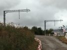
The `droppers` as mentioned by Fying Phil at the Braybrooke compound.IMG_1888.JPGIMG_1889.JPG

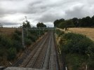
Looking south from Pipewell Road bridge in Desborough. This where the masts end before the Desborough gap.IMG_1893.JPG
 
Last edited:

Flying Phil

Established Member
Joined
18 Apr 2016
Messages
1,925
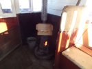
Thanks for the correction Elecman. I must confess though, my version of a stove pipe is a bit different (Sorry to go OT)
DSCF7350 pie and chips.JPG
 

Flying Phil

Established Member
Joined
18 Apr 2016
Messages
1,925
Ha Ha Nice stove Flying Phil!
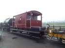
Up Early PJM! The stove is in my shed.....on wheels.....on the GCR
DSCF7335.JPG

And - of course, I am looking forward to looking down onto the electrified MML when travelling up to Ruddington behind the Windcutter trucks!!
 
Last edited:

Flying Phil

Established Member
Joined
18 Apr 2016
Messages
1,925
We were at Wistow this afternoon and there is another works compound being built there on the West side of the line near Kibworth outskirts.
 

GRALISTAIR

Established Member
Joined
11 Apr 2012
Messages
7,862
Location
Dalton GA USA & Preston Lancs
I'm fairly sure the Hope Valley Line's getting no further extension of wiring beyond Hazel Grove. MML wires will come first.
Though if memory serves, the Grid Feeder will be located fairly close to the junction of the Hope Valley line. But yes, MML first and I think Hope Valley will be quite a bit lower down on the priority list for electrification. Calder Valley Line will be ahead of Hope Valley.
 

Cowley

Forum Staff
Staff Member
Global Moderator
Joined
15 Apr 2016
Messages
15,756
Location
Devon
Some of the stuff about the ability of the UK to do large engineering projects is a new thread below.
Let’s stick to the MML stuff in this one now please.

Thanks everyone


Killingworth

Established Member
Joined
30 May 2018
Messages
4,868
Location
Sheffield
Though if memory serves, the Grid Feeder will be located fairly close to the junction of the Hope Valley line. But yes, MML first and I think Hope Valley will be quite a bit lower down on the priority list for electrification. Calder Valley Line will be ahead of Hope Valley.
MML to Sheffield by 2030 seems optimistic but I suspect the Hope Valley line might see wires through Dore station for contingency purposes and perhaps as far as the new Dore West Junction, and maybe round the Dore curve. But that's just my speculation. Getting the Sheaf Valley and Sheffield station reconfigured is going to be a mighty headache before anyone seriously plans and costs Hope Valley. Connecting with Leeds and Doncaster would probably be easier, cheaper and more helpful.
 

38Cto15E

Member
Joined
1 Nov 2009
Messages
999
Location
15E
How many bridges still have to be re-built between Kettering North jct and Market Harborough station? I have just watched a Don Coffey video and my guess is 5, one just north of Glendon and Rushton, 2 in Desborough and 2 between the A6 bypass bridge and Little Bowden.
 

59CosG95

Established Member
Joined
18 Aug 2013
Messages
6,488
Location
Between Peterborough & Bedlington
How many bridges still have to be re-built between Kettering North jct and Market Harborough station? I have just watched a Don Coffey video and my guess is 5, one just north of Glendon and Rushton, 2 in Desborough and 2 between the A6 bypass bridge and Little Bowden.
The first one of these (SPC3-42, just east of the Rushton compound) is being rebuilt at the moment. Intel is that the easternmost of the two bridges you mention between the A6 & Little Bowden is also being rebuilt, but as it is a private farm bridge, pictures are harder to come by.

Desborough hasn't been touched yet.
 

Flying Phil

Established Member
Joined
18 Apr 2016
Messages
1,925
Hi 38Cto15E
I believe that, in one or two locations, the track is due to be lowered to gain the needed clearances.
 

snowball

Established Member
Joined
4 Mar 2013
Messages
7,711
Location
Leeds
Hi 38Cto15E
I believe that, in one or two locations, the track is due to be lowered to gain the needed clearances.
There was a report last October that work was due to start last December to lower the track under two bridges between Kettering and MH.
 

59CosG95

Established Member
Joined
18 Aug 2013
Messages
6,488
Location
Between Peterborough & Bedlington
The first one of these (SPC3-42, just east of the Rushton compound) is being rebuilt at the moment. Intel is that the easternmost of the two bridges you mention between the A6 & Little Bowden is also being rebuilt, but as it is a private farm bridge, pictures are harder to come by.

Desborough hasn't been touched yet.

That being said, I've had a look on Kettering Borough Council's website, and the following applications should be of interest to people on here:
  • NK/2021/0633 - Bridge SPC3/42 (Rushton) - shows details of new bridge reconstructed in place of existing.
  • NK/2021/0748 - Bridge SPC3/39, Harborough Rd (B576) - shows details of bridge parapet alterations to facilitate electrification.
  • NK/2021/0745 - Bridge SPC3/40, Pipewell Rd - shows details of bridge parapet alterations to facilitate electrification.
  • NK/2021/0775 - Bridge SPC3/34 (Three Arch Bridge), Braybrooke - shows details of bridge parapet alterations to facilitate electrification.
  • NK/2022/0389 - Bridge SPC3/35 (Newtons Bridge), Braybrooke - shows details of new bridge installed to south of existing, and removal of existing bridge
  • NK/2022/0407 - Bridge SPC3/42 (Rushton) - shows details of revised approach on Up Main side following bridge reconstruction
(no such joy yet on the Harborough District Council Website btw)

Edit to add NK/2022/0037 - Bridge SPC3/38 (Judges Bridge), Desborough - shows details of bridge parapet and elevation alterations to facilitate electrification. Bridge to be jacked.
 
Last edited:

Top