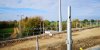
Non sensical weak points here. If anyone can explain this design please?
As others have explained bolts are common way of attaching things.
This looks to me like a sensible way of attaching the stanchion to the steel pile. The only slightly surprising element is the adapter on top of the top pile to provide vertical bolt locations, GWR piles have the pile and bolt sockets (bosses) integrated into a single component rather than two pieces. I guess the civils team specifying didn't have confidence of driving the pile spot on so have opted for a high tolerance solution.
The bolts provide an opportunity to position and plumb initially and later on over the life readjust should the ground move significantly. The stanchion base is actually slotted to allow for horizontal adjustment and bolts/washers allow for vertical adjustment.
The nuts/bolts will be inspection items to checked on an agreed schedule much like the bolted stanchion clamp being used to hold the mast

When the bolt/nut/washers become end of life you just need to change them, nothing particular major in terms of work complexity.
The method used for previous BR era mass concrete pads could best be summed up as 1. dig a hole 2. insert anchor bolts in cones 3. fill hole with concrete 4. "crack" the bolt from concrete whilst it's still green. 5. offer up stanchion 6. shim/level stanchion from base with steel shim plates. 7. tighten nuts 8. fill the cone with grout (and possibly the complete stanchion base) 9. Hope the ground does move later.
This was and is a very cheap way of forming bases but has the significant drawback of only working in good ground conditions and when the ground moves later has no simple way of readjusting to level and plumb. The bolts having been "set" and thus lost horizontal tolerance.
Sorting out for example lean later after many years is a major civils project requiring a new base to be formed and all the associated to the OLE works.
One of those situations where you spend more up front to have lower costs later (and possibly a longer life).
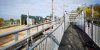
 Today. Sharnbrook tunnel. Nothing new here. Scaffolding is for temporary walk bridge whilst road is raised or elevated


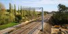
") There was track relaying going on, on the up (Fast) line between Kettering Jct (North) and the overbridge, whether this included any replacement pointwork I am not sure. Probably there was other work going on between Glendon and Leicester as well, maybe Market Harborough.
There was track relaying going on, on the up (Fast) line between Kettering Jct (North) and the overbridge, whether this included any replacement pointwork I am not sure. Probably there was other work going on between Glendon and Leicester as well, maybe Market Harborough.