• Our booking engine at tickets.railforums.co.uk (powered by TrainSplit) helps support the running of the forum with every ticket purchase! Find out more and ask any questions/give us feedback in this thread!

Rack railway engagement

Status
Not open for further replies.

RedPostJunc

Member
Joined
10 Aug 2021
Messages
125
Location
Andover
Apologies if this has been asked before, I did various searches and could not find anything relevant.

I have just returned from holiday in Switzerland and my travels included some rack railway travel. On some rack lines the whole network is racked, but on the line between Visp and Zermatt the steep bits are racked but the more level stretches are not racked.

There is a very noticeable bang and jolt as the train engages the rack. This made me wonder whether there is any wheel slide as the train engages the rack, even at slow speed?
 
Sponsor Post - registered members do not see these adverts; click here to register, or click here to log in
R

RailUK Forums

ac6000cw

Established Member
Joined
10 May 2014
Messages
3,157
Location
Cambridge, UK
I assume there can be a bit of slip, because the 'teeth' on the rack and the pinion/cogwheel have to be moved into alignment as the train runs onto the rack section. It might also depend if there are separate propulsion systems for rack (driving the cog) and adhesion (driving the wheels) modes.

See this Wikipedia entry on 'Rack-and-adhesion' railways - https://en.wikipedia.org/wiki/Rack_railway#Rack-and-adhesion_or_pure-rack - and the interesting photo from there of a 'Traction transition section' (below):

1920px-Abt_traction_transition.JPG
 

P Binnersley

Member
Joined
30 Dec 2018
Messages
436
The first (white) section of the rack is sprung so the rack will be depressed until it engages. The next section has high guard rails so that if the rack doesn't engage the engine will rise up until it supported on the rack wheel which will then very quickly fall into mesh.

I'm not sure if it is standard rack of some form of "Syncromesh" to assist engagement.
 

STEVIEBOY1

Established Member
Joined
31 Jul 2010
Messages
4,001
There is, or was, a steep rack section on the line between Luzern and Interlaken.
 

ac6000cw

Established Member
Joined
10 May 2014
Messages
3,157
Location
Cambridge, UK
There is, or was, a steep rack section on the line between Luzern and Interlaken.
It's the 'Brünig' line - it has three rack sections (two on the north side of the Brünig pass and one on the south side), with a maximum 12% rack gradient. Very nice ride, had a round trip over it a couple of times.

The first (white) section of the rack is sprung so the rack will be depressed until it engages. The next section has high guard rails so that if the rack doesn't engage the engine will rise up until it supported on the rack wheel which will then very quickly fall into mesh.

I'm not sure if it is standard rack of some form of "Syncromesh" to assist engagement.
Thanks for the info - zooming into the photo, on the left part of the transition system (between the guard rails) the thickness of the teeth varies from thin to normal thickness, presumably to allow the pinions on the train to ease into the rack - as you say, a form of "Syncromesh". Also that part only has a single row of teeth, instead of the offset double row that is normal for an 'Abt' rack (as on the far left).
 

hexagon789

Veteran Member
Joined
2 Sep 2016
Messages
15,791
Location
Glasgow
Apologies if this has been asked before, I did various searches and could not find anything relevant.

I have just returned from holiday in Switzerland and my travels included some rack railway travel. On some rack lines the whole network is racked, but on the line between Visp and Zermatt the steep bits are racked but the more level stretches are not racked.

There is a very noticeable bang and jolt as the train engages the rack. This made me wonder whether there is any wheel slide as the train engages the rack, even at slow speed?
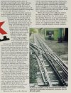
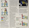
On systems where the rack gear wheel and rail wheels are on the same axle there is a permanent degree of slip to the rail wheels when using the rack.

As the rail wheels wear down, but the gear tooth maintains a set level of purchase on the rack, so the rail wheels will rotate slightly slower than the actual road speed. Because of this the gear wheels are set to provide an axle rotation equal to approximately the midlife size of the rail wheels. So on new wheels, when using the rack, the rail wheels effectively slip at a faster rate than passage over the track, and on worn wheels they slip at a slower rate.

Maximum adhesion is actually achieved under a slight slip, and a small degree of slip can be tolerated. The rack has the advantage of automatically controlling this slip at all times because the gear tooth is fixed with the rack at all times under use.
 

edwin_m

Veteran Member
Joined
21 Apr 2013
Messages
24,924
Location
Nottingham
On systems where the rack gear wheel and rail wheels are on the same axle there is a permanent degree of slip to the rail wheels when using the rack.

As the rail wheels wear down, but the gear tooth maintains a set level of purchase on the rack, so the rail wheels will rotate slightly slower than the actual road speed. Because of this the gear wheels are set to provide an axle rotation equal to approximately the midlife size of the rail wheels. So on new wheels, when using the rack, the rail wheels effectively slip at a faster rate than passage over the track, and on worn wheels they slip at a slower rate.

Maximum adhesion is actually achieved under a slight slip, and a small degree of slip can be tolerated. The rack has the advantage of automatically controlling this slip at all times because the gear tooth is fixed with the rack at all times under use.
How does that work? If they are on the same axle then this implies that some of the time, the diameter over the gear tooth must be greater than the wheel diameter. But won't it then strike the rail when going over a set of points?
 

hexagon789

Veteran Member
Joined
2 Sep 2016
Messages
15,791
Location
Glasgow
How does that work? If they are on the same axle then this implies that some of the time, the diameter over the gear tooth must be greater than the wheel diameter. But won't it then strike the rail when going over a set of points?
I don't know, I'm just repeating a segment of a piece I read in an issue of Railway Magazine. Should be easy to find it, I read it only yesterday.
 

30907

Veteran Member
Joined
30 Sep 2012
Messages
18,047
Location
Airedale
I don't know, I'm just repeating a segment of a piece I read in an issue of Railway Magazine. Should be easy to find it, I read it only yesterday.
I would have thought the principal wear is on the face of the cogwheel where it engages with the rack, so roughly perpendicular to the rail.
 

hexagon789

Veteran Member
Joined
2 Sep 2016
Messages
15,791
Location
Glasgow
How does that work? If they are on the same axle then this implies that some of the time, the diameter over the gear tooth must be greater than the wheel diameter. But won't it then strike the rail when going over a set of points?
I would have thought the principal wear is on the face of the cogwheel where it engages with the rack, so roughly perpendicular to the rail.
I've put the relevant bit of the article below:

Screenshot_20220622-153523_Samsung Internet.jpgScreenshot_20220622-153528_Samsung Internet.jpg
 

edwin_m

Veteran Member
Joined
21 Apr 2013
Messages
24,924
Location
Nottingham
I've put the relevant bit of the article below:

View attachment 116571View attachment 116572
Thanks for that. The text you quoted previously relates to figure 1(B). If I'm interpreting this correctly the pinion(yellow) surrounds the axle but is not directly attached to it. Instead it is connected via gearing (red) which allows the pinion to rotate at a higher revolutions per minute than the wheelset, so that (in the mid-state of wheel wear) the teeth of the smaller pinion are moving at the same speed (relative to the locomotive) as the tread of the larger wheel.

At least that's my o-pinion.
 

hexagon789

Veteran Member
Joined
2 Sep 2016
Messages
15,791
Location
Glasgow
Thanks for that. The text you quoted previously relates to figure 1(B). If I'm interpreting this correctly the pinion(yellow) surrounds the axle but is not directly attached to it. Instead it is connected via gearing (red) which allows the pinion to rotate at a higher revolutions per minute than the wheelset, so that (in the mid-state of wheel wear) the teeth of the smaller pinion are moving at the same speed (relative to the locomotive) as the tread of the larger wheel.

At least that's my o-pinion.
It was the wording in relation to the wheels slipping at a speed either slower or faster than actual road speed, while the gearwheel for the rack was at a fixed speed. The part from the last paragraph in the middle column of the first page onwards.

That was the bit that implied some form of controlled slip
 

edwin_m

Veteran Member
Joined
21 Apr 2013
Messages
24,924
Location
Nottingham
It was the wording in relation to the wheels slipping at a speed either slower or faster than actual road speed, while the gearwheel for the rack was at a fixed speed. The part from the last paragraph in the middle column of the first page onwards.

That was the bit that implied some form of controlled slip
Yes I agree there will be controlled slip as the wheels wear down. Mention of "on the same axle" suggested to me that the pinion was rigidly fixed to the axle so at the same rotational speed and would have to be roughly the same diameter as the wheels, but on further investigation this is not so.
 
Status
Not open for further replies.

Top