• Our booking engine at tickets.railforums.co.uk (powered by TrainSplit) helps support the running of the forum with every ticket purchase! Find out more and ask any questions/give us feedback in this thread!

Two pantographs in use.

Status
Not open for further replies.

citycat

Member
Joined
18 Dec 2013
Messages
241
Location
Woerden, The Netherlands
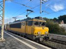
A friend is currently on the Berlin to Amsterdam IC. He wants to know why they use two pantographs on the NS when the lead pantograph is more likely to entangle on the wires?

As the loco was hooking up to the consist at Bad Bentheim when he took the photo, maybe it was for low speed operation?
 

Attachments

  • IMG_6939.jpeg
    IMG_6939.jpeg
    2.3 MB · Views: 147
Sponsor Post - registered members do not see these adverts; click here to register, or click here to log in
R

RailUK Forums

paul_munich

Member
Joined
23 Dec 2019
Messages
71
Location
Munich
The energy demand of the whole train is so high that the overhead line would kind of melt under 1,5kV.

When the train is moving they only use one panto.
 

DanielB

Member
Joined
27 Feb 2020
Messages
969
Location
Amersfoort, NL
I doubt it will really melt the OHLE, but it is indeed mandatory to have two pantographs up due to the high energy demand when carriages with air conditioning are attached. But only when stationary (to spread the current over two locations on the overhead lines).

It's also not only the class 1700, also class 186 automatically raises two pantographs when stationary with carriages attached. And apparently DDZ as well.
 

popeter45

Member
Joined
7 Dec 2019
Messages
1,113
Location
london
1.5Kv is 16X the current draw of 25Kv
also you will notice its uses 2 wires overhead to further reduce the per contact load

16x amp load spead across 4 contact points is only 4x per contact so way more manageable
 
Last edited:

AndrewE

Established Member
Joined
9 Nov 2015
Messages
5,110
That's interesting, I haven't noticed that setup in my European travels.
The 2 wires are very close together; I presumed - incorrectly - that they’d create an electrical arc.
Why would they? they are at the same voltage and both positive (I presume) so there is no risk at all.
I have wondered whether the double wires are to help with current flow, or just because of junctions each end of the platform? At Crewe there are 3 wires through some platforms, not to supply current but because it is easier than terminating multiple wires from the junctions at both ends!
 

Sun Chariot

Established Member
Joined
16 Mar 2009
Messages
1,436
Location
2 miles and 50 years away from the Longmoor Milita
Why would they? they are at the same voltage and both positive (I presume) so there is no risk at all.
I have wondered whether the double wires are to help with current flow, or just because of junctions each end of the platform? At Crewe there are 3 wires through some platforms, not to supply current but because it is easier than terminating multiple wires from the junctions at both ends!
Yes, agreed. I'd initially presumed one wire was +ve and the other -ve; but, as you say, no risk of arc if the polarity is the same in both.
 

Halish Railway

Established Member
Joined
26 Apr 2017
Messages
1,728
Location
West Yorkshire / Birmingham
This is also done in France where 1.5 Kv DC electrification exists.

IMG_8587.JPG

In the Netherlands, the top and tail Intercity Direct and Beneluxtrains only have one pantograph raised on each locomotive when stationary as the load is spread between two locomotives.
 

MisterT

Member
Joined
12 Oct 2014
Messages
405
Location
The Netherlands
And apparently DDZ as well
DDZ does it automatically after 5 minutes at standstill (and also lowers the second pantograph automatically when the train starts moving again).
In the Netherlands, the top and tail Intercity Direct and Beneluxtrains only have one pantograph raised on each locomotive when stationary as the load is spread between two locomotives
One of the locomotives should have 2 pantographs raised when at standstill (the one feeding the coaches). But in the (rare) case that one of the pantographs is isolated, just one pantograph is ususally enough. Unless the power draw is more than 300A, at which point the MCB will open automatically to prevent damaging the overhead wires.
 

DanielB

Member
Joined
27 Feb 2020
Messages
969
Location
Amersfoort, NL
I have wondered whether the double wires are to help with current flow, or just because of junctions each end of the platform?
All 1,5 kV DC electrified routes in the Netherlands have double wires due to the low voltage and thus high amperage. Doesn't have to do anything with junctions, there you might encounter even more wires. (At the Ravenstein railway bridge there are four for example, as the OHLE of the second track continues on the bridge which is single track. Though only two are feeding the train, the other two cross the bridge way out of pantograph reach)
 

citycat

Member
Joined
18 Dec 2013
Messages
241
Location
Woerden, The Netherlands
Thanks for the replies.

While we're on the subject of electrification, three days a week I am to be found on the Dutch A16 driving my artic truck from Rotterdam to Brussels, so I tend to keep an eye out for what's travelling on the adjacent HSL high speed line and classic line.

Near to Breda, I notice that the intercity direct Traxx locos drop their pantographs and coast for quite a distance, presumably due to OHL voltage changes. The locos and coaches even coast where there is a steep incline at that part of the track.

Why is there a voltage change?

Why do they coast for quite a distance? Is it because the Traxx needs a minute or two to reconfigure to the new voltage?

What would happen if the speed of the train was so low due to signalling or other restrictions that it didn't have the momentum to coast through the voltage change area or even up that steep incline?

Why do I not see the Sprinter units or the Eurostar (Thalys) or Velaro sets with their pantographs dropped and coasting?

Perhaps our voltage experts could enlighten me.
 

MisterT

Member
Joined
12 Oct 2014
Messages
405
Location
The Netherlands
There is a voltage change-over from 1.5 kV DC to 25 kV AC when the trains change between the HSL and the classic line. Both voltages use different pantographs, so the trains have to drop the pantograph, change the voltage and once under the new voltage raise the new one.
You won't see the Eurostar (Red and Blue) drop their pantographs, because they continue on the HSL and don't enter the classic lines.
The reason it's such a long coasting distance there, is because it is not just a voltage change-over, but also a neutral section. The distance between the neutral section and the voltage change-over is too short to effectively close the main circuit breaker in-between, because by the time the HV systems are ready again, the MCB has to open again because of the VCO. That's why some drivers already drop the pantographs before the neutral section.
 

citycat

Member
Joined
18 Dec 2013
Messages
241
Location
Woerden, The Netherlands
So apologies if I appear stupid, but why not electrify to 25kv throughout? Why are there sections of line with different voltages?

Also, near where I fill up with cheap Belgian diesel at the border before returning to the Netherlands, I see a lineside sign with B crossed out and the NS underneath. Does that sign just denote the border between the two country rail systems or is there some signalling or voltage change taking place there.

Sorry for all the questions. It’s a quiet Saturday night on the Dutch telly.
 

Bemined

Member
Joined
28 May 2022
Messages
72
Location
Rotterdam, Netherlands
Historical reasons, different voltages were chosen by different countries (often even by different companies in the same country) and by the time they realised that an international standard would have been better, it was way to expensive to change. It's not just retrofitting all trains and substations, 25kV also requires different wires and can interfere with the signalling system so that needs to be replaced as well. And it might requires tunnels and/or viaducts to be replaced, some leave very little room for overhead wires and a higher voltage requires larger insulators that might not fit.
 

JonasB

Member
Joined
27 Dec 2016
Messages
944
Location
Sweden
So apologies if I appear stupid, but why not electrify to 25kv throughout? Why are there sections of line with different voltages?

There are no stupid questions. But as mentioned, different countries have chosen different systems for electrification. All systems have their advantages and disadvantages. 1500V DC was chosen in the Netherlands, it is very easy system since you can basically feed the voltage from the catenary straight to the electric motors and basically just need a wire from the wheels to the motor, a wire from the motor to the controller and a wire from the controller to the pantograph. (Although in reality it is a bit more complicated.) Other countries that electrified early chose 15 kV, 16 ⅔ Hz. In those countries the locos needed transformers onboard to reduce the voltage.

The drawback with 1500 V is that it can't deliver as much power as higher voltages can, so when the HSL-Zuid (the high speed line from Amsterdam to Belgium) was built in the beginning of this century is was built with 25 kV 50 Hz to allow for 300 km/h. Around the same time as HSL-Zuid was built, another rail line was being built with 25 kV in the Netherlands. The Betuweroute, which is built for freight trains to and from the port in Rotterdam so for this line 25 kV was chosen to allow for heavy freight trains.
 

popeter45

Member
Joined
7 Dec 2019
Messages
1,113
Location
london
The Betuweroute, which is built for freight trains to and from the port in Rotterdam so for this line 25 kV was chosen to allow for heavy freight trains.
one big issue with the Betuweroute is it still needs 1.5Kv for the junction between its eastern half and its western half south of rotterdam, alongside the german end being 16.5Kv makes anything wanting to use it needing to be tri-voltage
worst part is how easy it would have been to link to two 25Kv sides as the junction is already where HSL-zuid joins so could have extended its 25KV portion to where the western side splits from the mainline
 

AM9

Veteran Member
Joined
13 May 2014
Messages
14,295
Location
St Albans
There are no stupid questions. But as mentioned, different countries have chosen different systems for electrification. All systems have their advantages and disadvantages. 1500V DC was chosen in the Netherlands, it is very easy system since you can basically feed the voltage from the catenary straight to the electric motors and basically just need a wire from the wheels to the motor, a wire from the motor to the controller and a wire from the controller to the pantograph. (Although in reality it is a bit more complicated.) Other countries that electrified early chose 15 kV, 16 ⅔ Hz. In those countries the locos needed transformers onboard to reduce the voltage.
I think the 16 2/3Hz system (originally the German system) was set at that voltage because traction motors of the day could just about work on that low frequency, - 50Hz was out of the question. To this day, the whole German railway network is fed from a 16.7Hz owned by the railway.
Transformers were (and are still are) used to drop the line voltage to traction system levels, but over 100 years ago to provide the motors with DC would have involved rotary converters which were heavy and needed frequent maintenance. Suitable rectifiers weren't available for mobile use until mercury arc devices became commercial after WW2.

The drawback with 1500 V is that it can't deliver as much power as higher voltages can, so when the HSL-Zuid (the high speed line from Amsterdam to Belgium) was built in the beginning of this century is was built with 25 kV 50 Hz to allow for 300 km/h. Around the same time as HSL-Zuid was built, another rail line was being built with 25 kV in the Netherlands. The Betuweroute, which is built for freight trains to and from the port in Rotterdam so for this line 25 kV was chosen to allow for heavy freight trains.
On normal main lines the double 1500V catenary is very heavy and stiff because of the wire gauges used to carry the high currents. Running with both pantographs was part of the fixed to meet the high current demand. Where these trains run at express passenger speeds with both pantographs collecting power, the overall stiffness of the system reduces the chances of dewirement that on lighter OLE would be intolerant of the additional standing waves that that introduces.
 

MisterT

Member
Joined
12 Oct 2014
Messages
405
Location
The Netherlands
I don't think we've actually run with 2 pantographs raised in the Netherlands (but maybe in the far far past). The driver is supposed to lower the second pantograph somewhere between 5 km/h and 30 km/h, if it isn't done automatically.
 

Bemined

Member
Joined
28 May 2022
Messages
72
Location
Rotterdam, Netherlands
one big issue with the Betuweroute is it still needs 1.5Kv for the junction between its eastern half and its western half south of rotterdam, alongside the german end being 16.5Kv makes anything wanting to use it needing to be tri-voltage
worst part is how easy it would have been to link to two 25Kv sides as the junction is already where HSL-zuid joins so could have extended its 25KV portion to where the western side splits from the mainline
There have been studies to convert Kijfhoek to 25kV, but I believe in the end the costs did not outweigh the benefits. It also wouldn't make much sense before the construction works in Germany are completed as until then freight trains have to be diverted via Venlo way to often to allow AC only locomotives to be used. But also within in the Netherlands DC only locomotives are still in use these days.
 

JonasB

Member
Joined
27 Dec 2016
Messages
944
Location
Sweden
I think the 16 2/3Hz system (originally the German system) was set at that voltage because traction motors of the day could just about work on that low frequency, - 50Hz was out of the question. To this day, the whole German railway network is fed from a 16.7Hz owned by the railway.
Transformers were (and are still are) used to drop the line voltage to traction system levels, but over 100 years ago to provide the motors with DC would have involved rotary converters which were heavy and needed frequent maintenance. Suitable rectifiers weren't available for mobile use until mercury arc devices became commercial after WW2.
That's what I've heard as well. 16 ⅔ Hz was chosen as a compromise that would work fine, the motors could run on it and the voltage could be reduced onboard. Early railway electrification in Sweden actually used 15 Hz, but the frequency was later increased to 16 ⅔ Hz.

That's why you in general see 25 kV 50 Hz in countries that started electrifying late. Like Finland (1960s), Denmark (1980s), Portugal (1950s) or the UK.
 

contrex

Member
Joined
19 May 2009
Messages
886
Location
St Werburghs, Bristol
I don't think the current draw on starting a heavy train via one pantograph would easily 'melt' the OLE or destroy the panto, but I think the local heating repeated over and over again in the same place would not be good. By the way, I once saw a video of a 1500v SNCF loco starting a freight train, at dusk, from a siding, the track being a bit uneven, and as the loco got going it rocked and swayed. One or other of the pantos would arc and you could see the contact wire glowing red in that place and fading.
 

JonasB

Member
Joined
27 Dec 2016
Messages
944
Location
Sweden
I don't think we've actually run with 2 pantographs raised in the Netherlands (but maybe in the far far past). The driver is supposed to lower the second pantograph somewhere between 5 km/h and 30 km/h, if it isn't done automatically.
Although it has been done in northern Sweden. The Dm3s used to run with both pantographs raised to handle the large currents better.


DanielB

Member
Joined
27 Feb 2020
Messages
969
Location
Amersfoort, NL
Aren't these Dm3s effectively three locomotives, just like the newer Iore locomotives which are described at Wikipedia as consisting of two single ended locomotives?
In that case the situation is actually not that different than in the Netherlands, where the iron ore trains from the Rotterdam harbour to Germany are also hauled by two locomotives with both their pantographs up (photo).
 

JonasB

Member
Joined
27 Dec 2016
Messages
944
Location
Sweden
Aren't these Dm3s effectively three locomotives, just like the newer Iore locomotives which are described at Wikipedia as consisting of two single ended locomotives?

Originally: Maybe, it depends on how you define separate locomotive. When they where retired: No, they were single articulated locomotives.

The Iores on the other hand are single cab locos that usually run in pairs.
 

themiller

Member
Joined
4 Dec 2011
Messages
1,068
Location
Cumbria, UK
While I was in Japan about a month ago, I noted some emus around Tokyo with 5 pantographs up whilst under way. I don’t know what type they were but some went to Haneda airport and weren’t several units coupled.
 
Status
Not open for further replies.

Top