I was curious as to how the Victorians built stone viaducts.
Have I got the following sequence more or less correct:
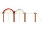
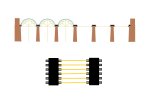
1. The abutments and piers / columns were constructed with the bases standing on / in solid rock.
2. Wooden arches are constructed and connect the piers together with supports.
3. Before the stone arches begin to be constructed the piers are reinforced,
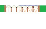
4. The stone arches are then constructed and side walls added.
5. To complete the process, the to be track bed area (middle section) is infilled with rubble etc.
6. The temporary wooden arches a removed.
Whilst all this is ongoing embankments (if needed) are constructed either side on the abutments.
To finish off of course, ballast and track are added.
Questions please:
I'm presuming (something I hate doing!) that all the temporary wooden arch bases would be in place before you started to build the sides of the stone arches?
Would you build one stone arch then move onto the next? or were the arches built up in tandem spreading the load on the piers?
Would the individual stone pieces be cemented together or just fit into place?
I've hear mention of a viaduct "Spring point" - what's that please?
Have I got the following sequence more or less correct:
1. The abutments and piers / columns were constructed with the bases standing on / in solid rock.
2. Wooden arches are constructed and connect the piers together with supports.
3. Before the stone arches begin to be constructed the piers are reinforced,
4. The stone arches are then constructed and side walls added.
5. To complete the process, the to be track bed area (middle section) is infilled with rubble etc.
6. The temporary wooden arches a removed.
Whilst all this is ongoing embankments (if needed) are constructed either side on the abutments.
To finish off of course, ballast and track are added.
Questions please:
I'm presuming (something I hate doing!) that all the temporary wooden arch bases would be in place before you started to build the sides of the stone arches?
Would you build one stone arch then move onto the next? or were the arches built up in tandem spreading the load on the piers?
Would the individual stone pieces be cemented together or just fit into place?
I've hear mention of a viaduct "Spring point" - what's that please?