So the original plan mentioned in a post further up this thread shows me using the Hornby Isolating rail, sawing them in half leaving one half of each connection on each side, that leaving the small black wire that come with it to make the power connection.
That all worked well enough, but I found, even after gluing the now half sections of the black plastic connector back to the track, it was very loose and a little catch of the base board on removal would pull them clean off. So although it worked, it needed to be changed.
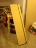
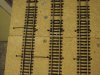
The first thing I need to mention is that you do not need to use the isolating rails, just any track with the fishplates removed, line them up together and tack them down firmly, I put extra track tacks through the sleepers close to the board edges, and as one of the following photos shows, I have packed up at least one of the tracks to make sure the join is smooth, leaving a rise between the two sections will cause the train to derail. Also, the tracks do not need to be that close they touch, you don't want them hanging over the edge of the baseboard or you may catch them and rip them off when removing the section.
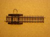
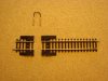
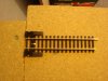
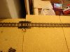
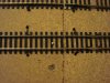
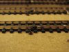
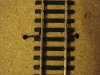
Shown if photos 1-4 you will see how I overcame the early problems I had, from track level view. The track at either side of the removable base board has a small black wire soldered to the outside side of the track (Obviously on the inside would derail the train). This wire is then passed down through a small hole drilled through the baseboard to the underside. The process is repeated for each individual rail. I have a 3 track section passing over the removable board, so that is 12 wires at one end, and 12 at the other. The photos will show what I'm talking about, Photo 1 showing a view of the track on both the main board and the removable section, with photo 4 being a view a single side.
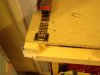
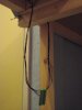
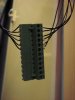
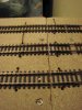
Photos 4 and 5 show the wires connected to a clip I sourced online, basically the corresponding wires from each individual rail connect to each other, so the currant continues to run, The clip separates so you can remove the base board, and there is one of these at each end. The photos show the 6 wires from the main fixed baseboard coming down to meet the 6 wires from the removable section, this is repeated at the other end.
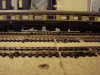
The final two photos, 6 and 7, show a complete view of the wiring from above, the only reason some of the wires do not drop straight through the baseboard right beside the track, is that there is supporting beams underneath, but the wires will be hidden by ballast anyway so makes no difference.
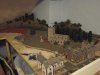
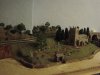
As I have not updated for quite a while, sorry, I have added a quick glimpse of some of my attempts at scenery, hope you enjoy, and I will upload some of the new stock and other bits and pieces soon.
Cheers, CSK