edwin_m
Veteran Member
I've pulled these from the Transpennine Upgrade site as it's really a wider question:
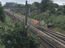
I think the relative benefits must be pretty marginal for double track. The Midland used TTCs almost exclusively on the double track sections between Bedford and Wellingborough but TRU appears to be using STCs except where there is a reason (such as signal sighting) to use TTCs instead. STC has more piles and masts to install, though they are smaller, but TTC needs an extra visit to site to crane in the boom before the cantilevers can be attached.
I understand the different role played by the SSA, but why the constant changes from TTC to STC.
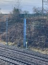
Do they have different advantages or disadvantages? There doesn't seem to be any pattern to it, often swapping one to the other as on the sweeping bend between the White Rose Centre footbridge and the Natasha Elliot footbridge for example. I would have thought simplicity and cost would mandate the use of TTC as often as possible? Less steel, fewer piles? What am I missing?
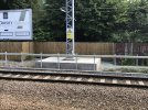
Regarding advantages and disadvantages, a single track cantilever of course requires much less steel and is less visually intrusive, however, when placed on the inside of a curve they can block the view of signals, hence twin track cantilevers are used on the approach to signals, with the supporting post placed on the outside of the curve. This has been standard practice with electrification since the OLE renewals on the WCML and after the Ladbrooke Grove crash which brought OLE structure and signal placements in the spotlight in the early 2000s.
I think the relative benefits must be pretty marginal for double track. The Midland used TTCs almost exclusively on the double track sections between Bedford and Wellingborough but TRU appears to be using STCs except where there is a reason (such as signal sighting) to use TTCs instead. STC has more piles and masts to install, though they are smaller, but TTC needs an extra visit to site to crane in the boom before the cantilevers can be attached.
")