Westinghouse
Member
- Joined
- 22 Jun 2014
- Messages
- 8
Does the return current on the 25kv Overhead System return via both running rails or just one ? I feel I should know this, but I don't !
Thanks.
Thanks.
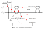
In layman terms that is correct, in general traction current normally returns through 1 railRegarding booster transformers, my understanding is that they would better be described as discouraging the return current from travelling through (or inducing current in) signalling cables. I believe this is done by passing the traction current through one side of the transformer, and the return conductor through the other side. The traction current passing through effectively sucks the return current through the other side. (Very technical description!)
Then why have booster transformers been omitted from some recent electrification schemes, and actually been removed in some places where they already existed on already electrified lines?The booster transformers maximise the efficiency of the return.
Then why have booster transformers been omitted from some recent electrification schemes, and actually been removed in some places where they already existed on already electrified lines?
(I'm referring to lines not equipped with an autotransformer system.)
Regarding booster transformers, my understanding is that they would better be described as discouraging the return current from travelling through (or inducing current in) signalling cables. I believe this is done by passing the traction current through one side of the transformer, and the return conductor through the other side. The traction current passing through effectively sucks the return current through the other side. (Very technical description!)
Correct. Just to add that most transformers have different numbers of coils in the primary and secondary. Ignoring the small losses in the transformer, the ratio of the voltages is the same as the ratio of the coils and the ratio of the currents is the inverse of this ratio. The booster transformer has the same number of primary and secondary coils, so forces the same current through the secondary (the return conductor) as is flowing in the primary (the catenary).This is a good way of explaining it.
To put it in slightly more technical terms, the induced current in the secondary winding of the booster transformer creates a potential difference that allows the return current from the rails to flow through the secondary winding into the return conductor. The return conductor is a low impedance path (impedance being a more complete description of resistance to current flow in an AC circuit, covering reactance as well as material resistance), so the current has a tendency to flow that way instead of flowing in the return rails, earth, or other cables such as signalling cables.
Correct. Just to add that most transformers have different numbers of coils in the primary and secondary. Ignoring the small losses in the transformer, the ratio of the voltages is the same as the ratio of the coils and the ratio of the currents is the inverse of this ratio. The booster transformer has the same number of primary and secondary coils, so forces the same current through the secondary (the return conductor) as is flowing in the primary (the catenary).
Many years ago I was involved in testing a navigation systems on trains, that was designed for road vehicles and used triangulation of long wave radio signals. It didn't work at all on electrified line, but it was noticeable that the signal to noise ratio was even worse on a section not fitted with return conductors and booster transformers. Having the return current in the return conductor close to the catenary induces less interference than if it is further away in the rails.
That's a slightly different issue. Stray current leaking out of the rails on DC systems causes big problems with corrosion of underground services, but being DC it can't be controlled with booster transformers. Attempts are therefore made to isolate the rails on DC systems from earth, though this can never be anywhere as good as an insulated return conductor.Yeah, very interesting! I am not a railway engineer myself but have some background in electrical engineering, and I can see the benefits of controlling EMF leakage by having current flow in a well insulated return conductor instead of in an unshielded third rail. Could play havoc on anything nearby or indeed on a train as you observed.
Booster Transformers and their corresponding lineside equipment were / are expensive to procure, install and maintain. Their purpose was to reduce lineside interference from the 25kV currents into copper signalling cables. Recent electrification schemes have benefitted from innovations such as fibre optic cables (for signalling and telecoms circuits) and now with the use of Return Screening Conductor (RSC), booster systems are becoming a thing of the past.Then why have booster transformers been omitted from some recent electrification schemes, and actually been removed in some places where they already existed on already electrified lines?
(I'm referring to lines not equipped with an autotransformer system.)

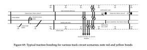
Yes they are. Many plain line parts of the railway also use jointless double rail track circuits, which have a matched frequency transmitter and receiver at a section's extremities. Different frequencies are used for adjoining sections with a 'tuned zone' at the boundary to clearly define it and prevent neighbouring sections interfering with one another. In jointless areas, traction current returns through both rails and is bonded across to other tracks and return conductors via impedance bonds, bulky items that sit in the 4 foot containing electrical wizardry connected across the rails forming a filter to only pass traction frequency current to or from either rail through its centre 'tap' without interfering with the track circuits. Elsewhere single rail track circuits are used, with one rail declared the signalling rail and the other the traction return rail. The traction rail can be parallel bonded while the signalling rail must be insulated from other return paths and serially bonded (so as to detect any discontinuity in the circuit). Similar techniques apply in DC territory, but different impedance bonds must be used, neither rail must ever be earthed (unless it's a dual electrified area!), and although modern jointless TCs are usually certified for both AC and DC use (with differing application restrictions and configuration), the choice of single rail track circuit is defined quite tightly by the electrification type. Simple DC track circuit types cannot be used in DC electrified areas, and 50 Hz (or any significant harmonic of 50Hz) TCs can't be used in AC electrified areas. Fortunately there are some TC types that can work with both systems or dual electrified areas would have been impossible before axle counters. Dual immune TCs must be AC or use some other changing waveform technique to work with DC traction and must have frequencies selected carefully to avoid 50Hz and its harmonics to work with AC traction. Where a double rail return system joins a single rail system there must be an impedance bond and insulated block joints. Engineers liked jointless track circuits because they avoided countless troublesome block joints on long plain line sections. They were the perfect partner for long welded rail and started to be used widely soon after LW rail became popular from the late 1960s. Using both rails for return also lowers the return resistance which is always beneficial. Unfortunately, double rail jointless arrangements cannot be used through junctions; single rail configurations must be used instead. Axle counters are best for traction return in AC and DC as all IBJs are avoided, on plain line and through junctions, and traction bonding can be placed almost anywhere relative to train detection sections. Impedance bonds are also avoided.In areas with AC electrification, and axle counters rather than track circuits, are both rails of a track bonded together?

