• Our new ticketing site is now live! Using either this or the original site (both powered by TrainSplit) helps support the running of the forum with every ticket purchase! Find out more and ask any questions/give us feedback in this thread!

Class 76 Pantographs: Why was the wire height so high?

Status
Not open for further replies.

Inversnecky

Member
Joined
1 Jan 2021
Messages
581
Location
Scotland
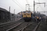
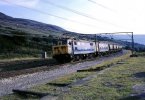
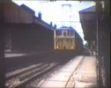
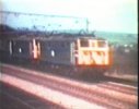
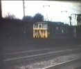
Looking at archive footage of 76s on the Woodhead line, I was struck by the extreme height of the pantographs at times.

What was the reason for this? At other times they are at a more normal height.

Presumably the overhead catenary was at a much higher height for some reason. Anyone know where and why?
 

Attachments

  • 7A11C247-A95A-4063-9A0B-FFB3214C586F.jpeg
    7A11C247-A95A-4063-9A0B-FFB3214C586F.jpeg
    175.3 KB · Views: 138
  • 55B35C9B-18BF-401C-86F1-0C10AE414490.jpeg
    55B35C9B-18BF-401C-86F1-0C10AE414490.jpeg
    192.6 KB · Views: 137
  • 117ED714-6ADD-490D-8EB1-77DDCF1F421C.jpeg
    117ED714-6ADD-490D-8EB1-77DDCF1F421C.jpeg
    183 KB · Views: 126
  • AF2E6D8D-D313-4F8F-BE23-25A912156459.jpeg
    AF2E6D8D-D313-4F8F-BE23-25A912156459.jpeg
    143.7 KB · Views: 123
  • 0D24653F-2D21-494C-8C26-B88EF3BF264E.jpeg
    0D24653F-2D21-494C-8C26-B88EF3BF264E.jpeg
    183 KB · Views: 135
Sponsor Post - registered members do not see these adverts; click here to register, or click here to log in
R

RailUK Forums

John Webb

Established Member
Joined
5 Jun 2010
Messages
3,467
Location
St Albans
First photo: Height required to fit OLE into existing stations?
Second photo: Appears to be a level crossing over the line - height needed to maximise clearance for road vehicles?
 

MikePJ

Member
Joined
10 Dec 2015
Messages
697
I'm only guessing here, but I suspect that when that overhead line was planned the engineers were a lot more conservative about "clearance distances" between live structures and anything else -to make sure that the power didn't arc across to rolling stock, train crew or structures. It was "only" 1500V (compared with 25kV now), but with the lines being used by steam locomotives blasting hot wet stuff up at the overhead wires, I suspect people took a "you can't be too careful" approach. Much later, BR did a series of experiments to prove that you could operate 25kV with relatively modest clearances even with a steam loco underneath - which was a surprising result. That resulted in the mixed-voltage electrification (25kV on open line, 6.25kV where clearances were reduced) being abandoned as unnecessary. So I could well believe that engineers previously didn't want to take too much risk with the earlier 1500V electrification.
 

Inversnecky

Member
Joined
1 Jan 2021
Messages
581
Location
Scotland
I'm only guessing here, but I suspect that when that overhead line was planned the engineers were a lot more conservative about "clearance distances" between live structures and anything else -to make sure that the power didn't arc across to rolling stock, train crew or structures.
Cheers. That makes sense, but there seems to have been variation on the same route.

It’s interesting that in the film, both pantographs are always up at the same time, so four up in the case of a double header.


Irascible

Established Member
Joined
21 Apr 2020
Messages
2,226
Location
Dyfneint
Cheers. That makes sense, but there seems to have been variation on the same route.

It’s interesting that in the film, both pantographs are always up at the same time, so four up in the case of a double header.


That OHL gear was sturdily built. I'd like to know how big the wire is compared to 25kV installs, actually.
 

3141

Established Member
Joined
1 Apr 2012
Messages
1,942
Location
Whitchurch, Hampshire
That OHL gear was sturdily built. I'd like to know how big the wire is compared to 25kV installs, actually.
It was DC and not AC. Someone may be able to tell us whether that was significant in relation to the clearances required. It would also be interesting to compare photos of pantographs on trains on the DC lines between Liverpool Street and Shenfield.
 

delticdave

Member
Joined
14 Apr 2017
Messages
449
It was DC and not AC. Someone may be able to tell us whether that was significant in relation to the clearances required. It would also be interesting to compare photos of pantographs on trains on the DC lines between Liverpool Street and Shenfield.
The 3-car sliding-door sets on both systems were almost identical. possibly different traction equipment, but that's all.

DC clearances were much smaller than the original 25kV AC systems, but the DC to 6.25kV AC changeover from Liverpool Street to Chelmsford & Southend in 1960 was accomplished over one weekend.
All of the existing DC wiring & insulators could cope with the higher voltage, just connecting the new AC feeder points & disconnecting the DC substations. They even maintained a basic passenger service with borrowed DMU's .

I don't have any suitable pix but from memory the catenary height at Ilford & & Reddish depots was circa 20 ft. above rail level,
probably to allow electric trains to pass through the washing plants without short-circuits. Also, said height would allow safer access to any roof-mounted items. (Ventilators, not the pantographs....) (When the EM2 society loco was stored at Ilford the pantographs were chained & padlocked down, just in case...)

Wire heights on the original G.E. lines varied, but they were always high at level crossings & some stations, including Chelmsford.

The replacement AC stock had to run under the high wires too, which is probably why all the UK single-arm pantographs are / (were?) larger than most European systems.

Sorry for the rambling, I was old enough to understand what was being done to my local railway but I couldn't afford a camera & film to record the changes.


PS, if you do want to see some very high 25 kV AC + very large pantographs, Youtube has some interesting videos of the new "electric dedicated freight railways", & the double-stack container trains.

DC
 

Inversnecky

Member
Joined
1 Jan 2021
Messages
581
Location
Scotland
I wonder if part of the reason was that the catenary wasn’t that level: there seems to be obvious sagging in places.

In other images, the pantographs are very low indeed.

PS, if you do want to see some very high 25 kV AC + very large pantographs, Youtube has some interesting videos of the new "electric dedicated freight railways", & the double-stack container trains.

I just saw a video of a high rise pantograph for a double stacked container train. Looks very precarious, and you wonder how the rails cope with the pressure!


Attachments

  • 6E50D047-54EB-4CCA-8076-E618B3055716.jpeg
    6E50D047-54EB-4CCA-8076-E618B3055716.jpeg
    314.8 KB · Views: 65
  • E6FD7C52-26E2-4F7D-9213-E3E8409AFB9C.jpeg
    E6FD7C52-26E2-4F7D-9213-E3E8409AFB9C.jpeg
    436.3 KB · Views: 59
  • 26F66154-7EB0-4D68-A945-2DC5279223F0.jpeg
    26F66154-7EB0-4D68-A945-2DC5279223F0.jpeg
    139.2 KB · Views: 51
  • 47A1F774-92A0-4D10-8F8D-DB6E32A49950.jpeg
    47A1F774-92A0-4D10-8F8D-DB6E32A49950.jpeg
    401 KB · Views: 54
  • D6C7B463-F10C-46AB-BC59-1751A78E46DF.jpeg
    D6C7B463-F10C-46AB-BC59-1751A78E46DF.jpeg
    476.8 KB · Views: 64
Last edited:

edwin_m

Veteran Member
Joined
21 Apr 2013
Messages
26,662
Location
Nottingham
Wire heights on the original G.E. lines varied, but they were always high at level crossings & some stations, including Chelmsford.

The replacement AC stock had to run under the high wires too, which is probably why all the UK single-arm pantographs are / (were?) larger than most European systems.
The high wiring at stations might have been to allow the use of a water column to top up a steam loco, or perhaps also the steam boilers that were fitted to the 77s.

I wasn't aware that British pantographs were larger, but the reason is probably to do with those level crossings. Our trains are a bit lower, and the pantograph sits in a recess rather than above the main roofline as with most Continental stock. Also our road vehicle clearances are higher than in most other countries, possibly because double deck buses are common here, so UK-only (road) trucks can be higher than those that cross to the Continent.

I believe Continental wire heights also vary, but perhaps by not so much. High Speed lines have a constant wire height, but Eurostars have to cope with the very high wires in the Channel Tunnel. The video in #9 is India, where they double stack on a flat wagon, not even a well wagon as used in North America, so I suspect that's the highest OLE anywhere.
 
Last edited:

Irascible

Established Member
Joined
21 Apr 2020
Messages
2,226
Location
Dyfneint
It was DC and not AC. Someone may be able to tell us whether that was significant in relation to the clearances required. It would also be interesting to compare photos of pantographs on trains on the DC lines between Liverpool Street and Shenfield.

Less interested in the clearance & more if a thicker conductor wire ( if it was - at 1500v I'd expect so ) helped reduce problems with multiple pans, tbh.
 

AM9

Veteran Member
Joined
13 May 2014
Messages
15,242
Location
St Albans
Less interested in the clearance & more if a thicker conductor wire ( if it was - at 1500v I'd expect so ) helped reduce problems with multiple pans, tbh.
Visually, no, the difference in voltage makes virtually no difference at all. The GEML conversion to ac, -first 6.25kV then 25kV, meant very little easement for HV clearance.
 

Bald Rick

Veteran Member
Joined
28 Sep 2010
Messages
32,062
That OHL gear was sturdily built. I'd like to know how big the wire is compared to 25kV installs, actually.

Less interested in the clearance & more if a thicker conductor wire ( if it was - at 1500v I'd expect so ) helped reduce problems with multiple pans, tbh.

Yes the D.C. wire was / is thicker. It had to be as the current was much higher; this is also why the D.C. locos had both pans up - for the large current draw.

I forget how much thicker the OLE is though - about 50% in terms of cross section I think. The heavier wire meant heavier catenary and supports. Certainly when the former D.C. parts of the GEML was rewired over the past decade, the weight of what came out was getting on for three times more than what replaced it.

If it helps, attached is a pic from the BR* archives of some (very) worn ex GE D.C. contact wire. That piece is 117mm long and weighs 180g. Put another way, a standard tension length of around a mile of contact wire will weigh around 3 tonnes. And that’s just the contact wire!

*Bald Rick, not the other BR.
 

Attachments

  • B1CD55B1-9361-44DC-8FDF-C54D59C4AC6C.jpeg
    B1CD55B1-9361-44DC-8FDF-C54D59C4AC6C.jpeg
    313.5 KB · Views: 80

AM9

Veteran Member
Joined
13 May 2014
Messages
15,242
Location
St Albans
Yes the D.C. wire was / is thicker. It had to be as the current was much higher; this is also why the D.C. locos had both pans up - for the large current draw.

I forget how much thicker the OLE is though - about 50% in terms of cross section I think. The heavier wire meant heavier catenary and supports. Certainly when the former D.C. parts of the GEML was rewired over the past decade, the weight of what came out was getting on for three times more than what replaced it.

If it helps, attached is a pic from the BR* archives of some (very) worn ex GE D.C. contact wire. That piece is 117mm long and weighs 180g. Put another way, a standard tension length of around a mile of contact wire will weigh around 3 tonnes. And that’s just the contact wire!

*Bald Rick, not the other BR.
I can remember the locations of the 6.25kV feed points/neutral section, - can you say whether they were the same as the locations when the line to Shenfield was DC?
 

bassmike

On Moderation
Joined
23 Aug 2010
Messages
143
Location
lenham kent
When the two class 319 units went through the Channel Tunnel to Coquelles, did the pan need any adjustment?
 

Bald Rick

Veteran Member
Joined
28 Sep 2010
Messages
32,062
I can remember the locations of the 6.25kV feed points/neutral section, - can you say whether they were the same as the locations when the line to Shenfield was DC?

I’ll have to check the authority on this - John Glover’s excellent book, ‘Eastern Electric’
 

nlogax

Established Member
Joined
29 May 2011
Messages
5,687
Location
Mostly Glasgow-ish. Mostly.
When the two class 319 units went through the Channel Tunnel to Coquelles, did the pan need any adjustment?

http://www.kentrail.org.uk/class_319_3.htm

Two units, Nos. 319008 and 319009 had two claims to fame over the 1993/1994 period. In 1993, the pair was dispatched to Chart Leacon Depot, Ashford, to receive modifications which would allow a higher vertical extension of the pantographs. The units were scheduled to transport a party of guests through the then recently completed Channel Tunnel, and the pantograph alterations were made in light of the higher level of the overhead wires, compared with those on the British Rail network.
 

Irascible

Established Member
Joined
21 Apr 2020
Messages
2,226
Location
Dyfneint
If it helps, attached is a pic from the BR* archives of some (very) worn ex GE D.C. contact wire. That piece is 117mm long and weighs 180g. Put another way, a standard tension length of around a mile of contact wire will weigh around 3 tonnes. And that’s just the contact wire!

*Bald Rick, not the other BR.

Robust indeed, wow. Putting all that up must have been fun!

I suspect no issues with standing waves etc at DC line speeds then ( I'd be surprised if the wire even moved much to be honest... ).
 

AM9

Veteran Member
Joined
13 May 2014
Messages
15,242
Location
St Albans
When the two class 319 units went through the Channel Tunnel to Coquelles, did the pan need any adjustment?
I believe that their maximum height limit devices were adjusted from their standard setting. Extending to reach the c. 20ft height in the tunnel was within the AMBR pantograph capability.
Oh it moved all right. Even with the aux wire.
Yes I remember that. The compound catenary and the heavier conductor (requiring a heavier catenary wire to support it) meant that the travelling wave was much slower and easier for the train to catch up, (which is when the danger of dewirement and damge was most likely). On the GEML, the trains were officially 75mph max but I've clocked* even the old 306s in their DC state at over 80mph coming down from Brentwood.
* Most of the electric lines were jointed track back then.
 

apk55

Member
Joined
7 Jul 2011
Messages
446
Location
Altrincham
The maximum height of the contact wire is normally determined by clearance at level crossings. Normal road vehicles are limited to 4.3M high so the contact wire has to be about 6M above ground to allow for safety clearance.
Popular photographic spots for the Woodhead line are often around level crossings (eg Torside) so the contact wire would be at near maximum height hence the pantographs would be at maximum extension.
 

billh

Member
Joined
7 Jan 2015
Messages
282
An interesting topic. At Guide Bridge Station, the overhead wiring comes well down to clear Guide Lane bridge, pantographs are nearly flat. Still in use at 25kV.
I can remember in the 1960's , the platform water columns were still working , at least one of them on platform 2 very close to the bridge, there cannot have been much safe headroom when watering a steam loco, though it is possible its use was restricted to side tank engines, slightly more safe. The columns were there for many years after steam went, complete with brazier basket to keep frost at bay . The level crossing at Dinting Lane had the wiring at a maximum height , possibly due to the way the road approaches the railway.
 

Merle Haggard

Established Member
Joined
20 Oct 2019
Messages
2,770
Location
Northampton
I don't know the answer to the question but I do have doubt about some of the suggestions. The high clearance was very noticeable. On the way into Wath shed in the 60's I took the attached photo - it's a dead end stabling siding but the clearance is still massive - certainly didn't occur only at level crossings.
The earlier 1500V D.C. electrification with an LNER involvement was the MSJ&A and I'm trying to remember details of that. Here's a photo I took bunking Altringham depot, and it's noteable because not only does the clearance also seem high, but it shows that Stone-Faiveley pans could also accommodate the height - a few of the units had their original diamond pans replaced.


Wath stabling sidings.jpgMSJA.jpg
 

AM9

Veteran Member
Joined
13 May 2014
Messages
15,242
Location
St Albans
The maximum height of the contact wire is normally determined by clearance at level crossings. Normal road vehicles are limited to 4.3M high so the contact wire has to be about 6M above ground to allow for safety clearance.
Popular photographic spots for the Woodhead line are often around level crossings (eg Torside) so the contact wire would be at near maximum height hence the pantographs would be at maximum extension.
On the GEML, there are pictures around of Ilford depot and Shenfield sidings with class 306s* having their pantographs fully extended, (* diamond types as they carried in their DC days). Here is one at the Ilford sheds:
https://d240vprofozpi.cloudfront.net/locos/Electric/shenfield_ilford.png
I can't find a shot of the Shenfield sidings but they were of similar height. At Gidea Park sidings, the height seemed to be the same as over open sections of the main line tracks which was 16ft. The OLE was required in many situations to go as low as possible as the GE structure gauge was not as generous as some other parts of the LNER. At Ilford for instance, the track was lowered so much that the already high platforms pose a constrint clearance for certain types of stock. Here is a picture taken before the original DC compound catenary was replaced, decades into 25kV use:
https://www.google.com/url?sa=i&url...ved=0CAIQjRxqFwoTCMD_udrilO4CFQAAAAAdAAAAABAz
 

Watford West

Member
Joined
20 Jul 2020
Messages
29
Location
Watford
It was interesting from Inversnecky 'film clip' that Indian Railways are using double-stack containers. In my naivety, I thought it was only the USA that had them. Does any other country in the world use double-stacks? I'd be interested to hear. Thanks
 

HSTEd

Veteran Member
Joined
14 Jul 2011
Messages
18,583
It was interesting from Inversnecky 'film clip' that Indian Railways are using double-stack containers. In my naivety, I thought it was only the USA that had them. Does any other country in the world use double-stacks? I'd be interested to hear. Thanks

They are used in Mexico, but mainly following US practice.
Only a few other countreis have adopted them.

Most interestingly Indian Railways can use double stack on top of ordinary flat wagons (unlike the US) because the wider track gauge makes the train more stable.
 
Last edited:

delticdave

Member
Joined
14 Apr 2017
Messages
449
They are used in Mexico, but mainly following US practice.
Only a few other countreis have adopted them.

Most interestingly Indian Railways can use double stack on top of ordinary flat wagons (unlike the US) because the wider loading gauge makes the train more stable.
I'd suspect that the wider track gauge (5ft 6in) is the real stability factor. Also, the 5-car double-stack sets have a lower platform than other I.R. container wagons. The special e-lok pantographs do have a very high reach, maybe more than any of the US e-loks?
 
Status
Not open for further replies.

Top