• Our new ticketing site is now live! Using either this or the original site (both powered by TrainSplit) helps support the running of the forum with every ticket purchase! Find out more and ask any questions/give us feedback in this thread!

GWML ATP

crablab

Member
Joined
8 Feb 2020
Messages
1,145
Location
UK
How operational is the GWML ATP?

I ask as it's 30 years' old now, and the contemporary installation on the Chiltern Lines was decommissioned a while ago.

Anecdotally, I've seen several ATP 'ramps' which look a bit mangled and missing their inner yellow piece, although the mushrooms are still omnipresent.

So I don't know how much of the system is still operational and how much it is used? I would hav expected some publicity if it was being gradually decommissioned, given the ORR requiring Chiltern to install TPWS to mitigate the SPAD risk.
 
Sponsor Post - registered members do not see these adverts; click here to register, or click here to log in
R

RailUK Forums

JN114

Established Member
Joined
28 Jun 2005
Messages
3,473
It is fully operational still; and GW-ATP fitted trains must have the equipment working to run in passenger service over fitted lines.

The Beacons are just a loop of aerial cable in sturdy housing. As long as the cable inside is intact minor damage to the structure of the beacon is not going to effect the ability for system to operate.


== Doublepost prevention - post automatically merged: ==

although the mushrooms are still omnipresent

They’re probably associated with Axle Counters on the GW

GW-ATP lineside equipment is housed in fairly standard trackside cabinets.

It was the CH-ATP system that housed some of the control electronics in little yellow “mushrooms” at the lineside
 

crablab

Member
Joined
8 Feb 2020
Messages
1,145
Location
UK
It is fully operational still; and GW-ATP fitted trains must have the equipment working to run in passenger service over fitted lines
Thanks!

What's the replacement strategy? GWML Modernisation envisioned complete replacement, but ETCS doesn't seem to have got further than Airport Junction.
 

JN114

Established Member
Joined
28 Jun 2005
Messages
3,473
What's the replacement strategy? GWML Modernisation envisioned complete replacement, but ETCS doesn't seem to have got further than Airport Junction.

No confirmed/committed plans to replace at present.

Expansion of ETCS L2 overlay as fitted between Ealing Broadway and West Drayton incl Heathrow would be the logical step.

The main issue with doing that is the hardware implementation for GW-ATP on the IETs makes it essentially impossible for them to operate under BOTH GW-ATP and ETCS. To use ETCS one would need to fully isolate ATP or vice versa. As reinstating those systems can only be done by a special technicians key, then it isn’t practical to transition from one system to the other on any kind of routine basis.
 

alxndr

Established Member
Joined
3 Apr 2015
Messages
1,605
I left the Western three years ago so my information is a little out of date, but certainly then it was fully operational, and there were spares on the shelf. We had recently got a new ground tester just before I left (somehow managing to make it even bigger and awkward than the old one!) and there was talks of life extension work, although I don’t know if that ever came to fruition.

The beacons are pretty sturdy things. Generally all that goes wrong, whatever their shape, is that they lose the ability to know they’re intact. This doesn’t actually affect their operation. The loops are a bit more prone to damage as they are just a loop of cable. Testing those to find the damage is time consuming, but it’s straightforward to joint back together as it is just a single core cable with a couple of resistors on the end.

The encoders themselves rarely go wrong, same with the current sensing APTLITs. When an encoder does get itself into deadlock a reset normally brings it back to life. In the 10 years I was on the Western I don’t think I ever personally had to change one, just reflow some dry solder joints on the resistors.

@Annetts key might have more recent knowledge as I’m pretty sure they’re Western based.
 

irish_rail

On Moderation
Joined
30 Oct 2013
Messages
4,338
Location
Plymouth
It's so operational that ATP needs to be "set up" still on the short HSTs that run wholly in Cornwall!
 

crablab

Member
Joined
8 Feb 2020
Messages
1,145
Location
UK
Thanks both - fascinating.

Interesting how robust GW ATP has turned out to be, despite misgivings about cost. I wonder, if Railtrack hadn't come along, whether we'd have seen more ATP rollouts.
There was a time when FGW had "ATP fitted" stickers on the side of their trains!
The encoders themselves rarely go wrong, same with the current sensing APTLITs. When an encoder does get itself into deadlock a reset normally brings it back to life.
Would you mind adding a bit more detail here? I'm following, but would like to understand more about how the ATP components work. I've not seen much public information: block diagrams, fault finding techniques etc.
and there were spares on the shelf
What's the vendor support like? Particularly with the significant resignallings and various track alterations of recent years.
 

Annetts key

Established Member
Joined
13 Feb 2021
Messages
3,003
Location
West is best
How operational is the GWML ATP?
As of April last year (2024), still in operational use.

Anecdotally, I've seen several ATP 'ramps' which look a bit mangled and missing their inner yellow piece, although the mushrooms are still omnipresent.
The beacons (rectangular metal "things") are made out of stainless steel and can take a hell of a whack before they fail. The plastic yellow piece was an after thought, it was not fitted originally to many of the first installations. And was abandoned on my area when it was discovered that the P.Way ignored the "don't step" wording anyway! It's purely cosmetic.

ATP has no mushrooms. It uses either small horizontal rectangular "dis. boxes" on metal stands, square metal "dis. boxes" mounted on sleepers or more normal vertical dis. boxes similar to those used for track circuits. The later are replacements for the earlier types.

So I don't know how much of the system is still operational and how much it is used?
All trains running at 125 MPH, in other words, the 80X use it. Further more, the "heathy" "okay" output from the ATP encoders are now connected to the SSI TFM (signal modules), so each ATP installation can be checked on the technicians terminal.

The Beacons are just a loop of aerial cable in sturdy housing. As long as the cable inside is intact minor damage to the structure of the beacon is not going to effect the ability for system to operate.
There is no cable in most of the beacon. The rectangular metal form is the secondary of a transformer.

GW-ATP lineside equipment is housed in fairly standard trackside cabinets.
The encoders (including their built-in power supply modules), a mains filter, fuses and the cable terminations are housed in stainless steel trackside cabinets. They are smaller (shorter) than a standard BRB location case.

What's the replacement strategy? GWML Modernisation envisioned complete replacement, but ETCS doesn't seem to have got further than Airport Junction.
Suppose to be ERTMS/ETCS. But the last date I saw was 2035 ~ 2040. But that was some time ago.

I left the Western three years ago so my information is a little out of date, but certainly then it was fully operational, and there were spares on the shelf.
As of April last year (2024), various spares were still available.

We had recently got a new ground tester just before I left (somehow managing to make it even bigger and awkward than the old one!) and there was talks of life extension work, although I don’t know if that ever came to fruition.
Um, the new ground testers were the same size. At least the new ones we had were. They no longer had a built-in PSU, the PSU ("charger") was separate. I never heard anything about life extension work.

However, as a result of a recommendation (from an accident investigation or incident I think, I forget the details), the gaps in the system between Bristol and Swindon that had been left (not all signals had been fitted when it was a pilot system under test) were filled in by brand new installations using brand new parts. I forget the date, but this was before the electrification of the GWML.

Then, when the signalling was renewed and re-controlled to TVSC, the ATP was retained and connected to the new system. Including moving/relocating or providing new equipment as required.

The beacons are pretty sturdy things. Generally all that goes wrong, whatever their shape, is that they lose the ability to know they’re intact. This doesn’t actually affect their operation.
The beacons have a "feedback" voltage. This tells the encoder that they are working. The most common fault is that this feedback voltage drops or is lost completely. Then the encoder flags this and drops out the "heathy" "okay" output. Although in most cases, the installation is still operational.

The loops are a bit more prone to damage as they are just a loop of cable. Testing those to find the damage is time consuming, but it’s straightforward to joint back together as it is just a single core cable with a couple of resistors on the end.
Finding hidden breaks of the copper core but where there is no easily noticeable damage to the rubber is a right royal pain. Rather annoyingly, I've since thought of a faster way of finding breaks. But I'm now no longer in the industry.

The encoders themselves rarely go wrong
The electrolytic capacitors in the built-in switch mode PSU are now causing some encoders to fail.

We have had a some of the mains filters fail. These stink when they go. Again, I suspect capacitor failure. But these are likely X2 paper types.

same with the current sensing APTLITs.
I don't remember any failures of these, apart from when the wiring got damaged.

Interesting how robust GW ATP has turned out to be, despite misgivings about cost. I wonder, if Railtrack hadn't come along, whether we'd have seen more ATP rollouts.

The use of APTLITs means that installation is far less intrusive compared to fitting TPWS. Everything else is effectively modular. So it's far faster and therefore likely cheaper to install a beacon only ATP signal installation compared to TPWS.

Would you mind adding a bit more detail here? I'm following, but would like to understand more about how the ATP components work. I've not seen much public information: block diagrams, fault finding techniques etc.

I'll add more tomorrow...

What's the vendor support like? Particularly with the significant resignallings and various track alterations of recent years.
I don't remember having or needing any technical support. We (local) S&T maintenance staff carried out all routine maintenance work and all fault investigations ourselves.

In terms of spares, I only know that new beacons were available, normally ordered in lot rather than individually. I *think* the *new* spare encoders may have been serviced units, but as they are supposed to sealed units, I didn’t look inside. They rather annoying have different labels on which makes selecting the correct type more difficult.
 
Last edited:

alxndr

Established Member
Joined
3 Apr 2015
Messages
1,605
Um, the new ground testers were the same size. At least the new ones we has were. They no longer had a built-in PSU, the PSU ("charger") was separate.
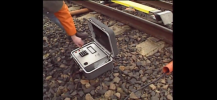
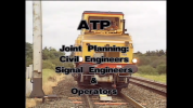
Possibly a slightly different design then, our PSU/charger had always been separate and remained the same. The first ones we had were as pictured in the “Living with ATP” video (screencap below), although significantly less square and held together with someone’s old belt by that point.
1747191498310.png

The newer ones came in a ruggedised orange plastic case with more internal padding and empty space to the side for storage. I’m not sure if it was actually heavier or just felt like it as it was bulkier.

I never heard anything about life extension work.
It was briefly spoken about as I came up with a checksheet with the intention of getting all our installations inspected to guide any necessary remedial works but it never came to anything before I left a month or so later so may have died a death shortly after.

The electrolytic capacitors in the built-in switch mode PSU are now causing some encoders to fail.

We have had a some of the mains filters fail. These stink when they go. Again, I suspect capacitor failure. But these are likely X2 paper types.
Only had the mains filters go myself. I remember replacing it but don’t remember the smell!

Would you mind adding a bit more detail here? I'm following, but would like to understand more about how the ATP components work. I've not seen much public information: block diagrams, fault finding techniques etc.
Have you come across the aforementioned video? It’s quite a good overview of the system.


There’s also this one, aimed more at the drivers’ perspective.


crablab

Member
Joined
8 Feb 2020
Messages
1,145
Location
UK
I'll add more tomorrow...
Thanks!
Have you come across the aforementioned video? It’s quite a good overview of the system.
Yup :) Unfortunately it's been the extent of my knowledge, until this thread.

Everything else is effectively modular. So it's far faster and therefore likely cheaper to install a beacon only ATP signal installation compared to TPWS.
One wonders why this wasn't recognised...
How problematic has the lack of updates between beacons been? The cable loops are there to help with this in theory.
Did the pilot installations provide any particular insights, other than the perceived cost?
 

Annetts key

Established Member
Joined
13 Feb 2021
Messages
3,003
Location
West is best
The ATP is not a replacement for the interlocking. The ATP receives the signal aspect information from a conventional signalling system. It has fixed data for the signal beacon number, the next signal beacon number, if this has an additional beacon, the type of overlap and all line speeds, permanent and junction speed restrictions.

The path of the signal aspect information is from the conventional signalling system to the ATP encoder. Then to the signal beacon, an additional beacon if needed. Plus where fitted, to an in-fill beacon or an in-fill loop (cable loop). All these transmit data to the antenna mounted on the underside of the train. This feeds the data to the trains on-board ATP computers.

GWML ATP – the basics of the ground equipment

The equipment comprises of:
• Lineside cabinet which contains an encoder
• Signal beacon
• Additional beacon
• In-Fill beacon
• In-Fill loop
• Dis-boxes
• APTLITs (in the normal location cupboard)
• Dummy load (in the normal location cupboard)
• Cables to interconnect these

Some screenshots and photos:

Lineside cabinet:
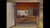
GWML ATP Lineside Loc showing encoder.png
(photo shows a lineside cabinet which is open and so you can see the encoder, mains filter, various resistors, fuse holders and cable terminals)
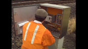
GWML ATP Lineside Loc showing encoder 2.png
(photo shows a lineside cabinet which is open with a person looking inside)

Encoder showing the two parameter plugs:
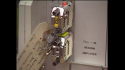
GWML ATP encoder and plugs.png
(photo shows a close up view of an encoder fitted with both of the two parameter plugs)

Signal beacon and the start of an in-fill loop:
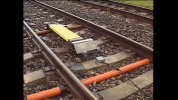
GWML ATP signal beacon and start of in-fill loop.png
(photo shows a beacon mounted on sleepers in the four foot, the dis-box for the start of the in-fill loop mounted on a sleeper next to the beacon and part of the single core cables that form the in-fill loop)
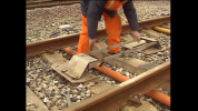
GWML ATP beacon inc dis box.png
(photo shows another view of a beacon, with a person working on the beacon, directly behind the person you can see the original horizontal type dis-box for the cable to the beacon)
GWML ATP beacon.png
(photo shows another view of a signal beacon, here you can see where it is in relation to the signal, the post of which is on the left, also on the left you can see the dis-box for the cable to the beacon mounted in the ballast shoulder)

APTLITs
GWML ATP - some 2BA APTLITs.JPG
(photo shows some 2BA electrical terminals fitted with 2BA type APTLITs)

One wonders why this wasn't recognised...
The sizeable costs come from an estimate of fitting EVERY signal on the network and the costs of fitting EVERY single train.

How problematic has the lack of updates between beacons been? The cable loops are there to help with this in theory.
Did the pilot installations provide any particular insights, other than the perceived cost?
That's difficult to say. The pilot installations had a mix of signal beacon only, signal beacon and in-fill beacon or signal beacon and in-fill loop. The length of the loops varied. The positions of the in-fill beacons were carefully selected.

Drivers had to learn to drive differently. If a signal is showing green, it's no problem, the train can be driven as normal. If the signal is showing a double yellow or a single yellow and does not change aspect as the train approaches, the driver must keep the speed of the train within the braking curve so that the train can stop short of the (potentially unseen) red signal ahead. If the signal is red, the train has to stop short of the signal, then when it clears move forward so that the on-board computers can receive the message from the signal beacon, which will now reflect the current displayed aspect.

The limitations are, that if a signal steps up to a less restrictive aspect after the train has passed the previous signal, the driver has to continue to obey the braking curve as if the signal has not changed aspect, until either, the on-board computers have received a new message from either, an in-fill beacon, an in-fill loop or worst case, the signal beacon at the signal. This gives the impression that the train is being delayed unnecessarily. But how much delay, if any is caused depends on a number of factors, if the train is following yellows because of a slower train ahead, in practice, there may be very little lost time.

For this reason, the train operator was against using ATP. But attitudes changed after the Ladbroke Grove rail crash.
 

crablab

Member
Joined
8 Feb 2020
Messages
1,145
Location
UK
Thank you for taking the time to put together the very informative post @Annetts key!
APTLITs (in the normal location cupboard)
What does the acrynom stand for? I'm still unclear what this is for; if it's in the location case and going by the photo, I'm assuming it's the connection between the APT encoder and the interlocking?

photo shows another view of a beacon, with a person working on the beacon
Where is the actual loop/beacon on the 4ft way installations? Most of it seems to be a steel frame, with or without yellow infill panel.

The sizeable costs come from an estimate of fitting EVERY signal on the network and the costs of fitting EVERY single train.
That feels like a rather ham fisted and unfortunate calculation, which some might say was designed to skew the outcome.

If the signal is red, the train has to stop short of the signal, then when it clears move forward so that the on-board computers can receive the message from the signal beacon, which will now reflect the current displayed aspect.
In this scenario, at what point does ATP trip?
My understanding is that ATP knows the beacon sequence and the distance between them. So in this example, it knows there's a beacon for a signal which was last updated as at danger.
So how much error margin is there to allow space to pull forward and receive the update for the now-clear beacon before ATP reckons it should have seen it and trips?

Encoder showing the two parameter plugs:
Were two sufficient? What about differential speeds?

The positions of the in-fill beacons were carefully selected.
Presumably they needed to be recalculated somewhat with the IETs, which have superior (de) acceleration curves?

How was resignalling handled? Presumably there's a register of the beacons and their encoding?
 

Annetts key

Established Member
Joined
13 Feb 2021
Messages
3,003
Location
West is best
What does the acrynom stand for?
Sorry, signal engineering is full of acronyms in addition to the general railway acronyms...
ATP Light (or lamp) Interface Transformer (ATPLIT)
I'm still unclear what this is for; if it's in the location case and going by the photo, I'm assuming it's the connection between the APT encoder and the interlocking?
It's fitted in the location case for the existing signalling system. It's a current transformer. The 110V AC current flows through the primary winding which is in series with the feed to the signal, this then causes a current in the secondary which feeds to the encoder in the ATP enclosure.

On some SSI (Solid State Interlocking) schemes, a direct 110V AC supply from the SSI signal module is used, it's fed to the ATP enclosure.

Where is the actual loop/beacon on the 4ft way installations? Most of it seems to be a steel frame, with or without yellow infill panel.
A beacon is the "steel frame". It acts as a transmitting antenna.
A loop is two lengths of single core cable. One cable runs along the foot of the cess rail (but on the four foot side). The other runs along the centre line of the sleepers. At defined distances, the cables swap over. Both cables start at a dis-box and end at another dis-box. They form an electrical loop, which acts as a transmitting antenna.

That feels like a rather ham fisted and unfortunate calculation, which some might say was designed to skew the outcome.
"You might very well think that; I couldn't possibly comment"...

In this scenario, at what point does ATP trip?
My understanding is that ATP knows the beacon sequence and the distance between them. So in this example, it knows there's a beacon for a signal which was last updated as at danger.
So how much error margin is there to allow space to pull forward and receive the update for the now-clear beacon before ATP reckons it should have seen it and trips?
I can't answer that, but the train is allowed to move forward at a slow speed, known as "release speed". Also there is a tolerance in the distances due to wheel slip and wheel slide that the train may experience.
A driver or someone who knows more about the traction side may be able to give a better answer.

Were two sufficient? What about differential speeds?
One plug contains ALL the fixed data, including ALL speed information that is required. Differential speeds - I don't know how these are handled, keep in mind that at the moment, only high speed passenger trains are fitted, so they would all be using the higher speed.
The second plug is used if a TSR (temporary speed restriction) (which is fully supervised) or an ESR (emergency speed restriction) (which is unsupervised) is needed. If there is no TSR or ESR, a "NO SR" plug is fitted.

Presumably they needed to be recalculated somewhat with the IETs, which have superior (de) acceleration curves?
As far as I know, there was no programme to move them. The determination is more about where the signal can be see from.


How was resignalling handled? Presumably there's a register of the beacons and their encoding?
Yes, there are records.
 

alxndr

Established Member
Joined
3 Apr 2015
Messages
1,605
Sorry, signal engineering is full of acronyms in addition to the general railway acronyms...
ATP Light (or lamp) Interface Transformer (ATPLIT)
Plus ATPLIT is almost exclusively pronounced as a word in my experience, and a word that’s morphed into something closer to “Atlip” to my ears. If you spelled it out most people would give you a strange look and have to have a think about what you were referring to.
The second plug is used if a TSR (temporary speed restriction) (which is fully supervised) or an ESR (emergency speed restriction) (which is unsupervised) is needed. If there is no TSR or ESR, a "NO SR" plug is fitted.
At add, the TSR and No SR plugs are kept in the enclosure on a chain so they cannot be lost. The TSR plugs are programmed when the speed is designed to suit the speed restriction that’s being implemented and needed to be collected and taken to site.
 

Annetts key

Established Member
Joined
13 Feb 2021
Messages
3,003
Location
West is best
Possibly a slightly different design then, our PSU/charger had always been separate and remained the same. The first ones we had were as pictured in the “Living with ATP” video (screencap below), although significantly less square and held together with someone’s old belt by that point.

The newer ones came in a ruggedised orange plastic case with more internal padding and empty space to the side for storage. I’m not sure if it was actually heavier or just felt like it as it was bulkier.
So, as far as I am aware, there were three different designs:
  • The original (supplied as part of the scheme, as in the screen shot from the video) in a metal case, that had the charger built-in. You connected an IEC ("kettle") mains lead to charge it up. The battery inside was (I think) four Ni-Cad cells (D-type/size I think). We replaced some when they failed.
  • The second type came in the same type of metal case, but these used an external battery charger. Otherwise they functioned the same.
  • The third type, like you describe, in an orange plastic case. They functioned the same. I don't remember the case being significantly bigger or heaver, but then by that stage, I wasn’t the one normally carrying it :lol:
 

alxndr

Established Member
Joined
3 Apr 2015
Messages
1,605
We had the second and third varieties then, I’m too young to have experienced the first.

The third variety was definitely worse to carry as it fascinated us that they’d managed it! At a guess it was an extra 6 inches wider and slightly deeper too.
 

TurboMan

Member
Joined
5 Apr 2022
Messages
422
Location
UK
To use ETCS one would need to fully isolate ATP or vice versa. As reinstating those systems can only be done by a special technicians key, then it isn’t practical to transition from one system to the other on any kind of routine basis.
There is an ETCS - BR-ATP selection switch on the cab back wall which is operated with a driver's key, but doesn't need a flag key to unlock it. Neither system is being isolated, it's more that the driver is telling the train which system to use.

The more problematic issue is that there is no means of transitioning from ATP to ETCS and vice versa dynamically (i.e. on the move) as there is between ETCS levels. So in theory the driver could switch between ATP and ETCS but only at a stand (though I dread to think how long it would take!) - in fact for a while, Hitachi depot drivers would switch to ETCS to move units around on depot, rather than go through the whole ATP set up rigmarole.
 

zwk500

Veteran Member
Joined
20 Jan 2020
Messages
15,491
Location
Bristol
There is an ETCS - BR-ATP selection switch on the cab back wall which is operated with a driver's key, but doesn't need a flag key to unlock it. Neither system is being isolated, it's more that the driver is telling the train which system to use.

The more problematic issue is that there is no means of transitioning from ATP to ETCS and vice versa dynamically (i.e. on the move) as there is between ETCS levels. So in theory the driver could switch between ATP and ETCS but only at a stand (though I dread to think how long it would take!) - in fact for a while, Hitachi depot drivers would switch to ETCS to move units around on depot, rather than go through the whole ATP set up rigmarole.
Out of interest, how does the setup procedure for ATP differ from ETCS, particularly in the time taken to do it?
 

TurboMan

Member
Joined
5 Apr 2022
Messages
422
Location
UK
Out of interest, how does the setup procedure for ATP differ from ETCS, particularly in the time taken to do it?
ATP has to do a self-test every time the cab is activated. There is a long self-test which seems to take forever, but is probably only a couple of minutes or so, or there's a short self-test which takes about 60 seconds - but you only get the short version if you're pressing the 'on' button on the ATP speedo panel as the cab is being activated.

Once the self-test is complete, the driver has to enter their PIN, and confirm train length and any non-standard data (used if there is a defect related speed restriction - surprisingly, that's something that ETCS can't do) via a keypad - that probably takes 30 seconds or so, mainly because the software/hardware is so antiquated (it feels like trying to open a Web page using a 56k modem).

In comparison SoM for ETCS probably takes 30 seconds in total.
 

crablab

Member
Joined
8 Feb 2020
Messages
1,145
Location
UK
@TurboMan What's the interface like on the Hitachis? The old data entry panel was a separate device, but I presume all the ATP stuff is now integrated into the standard TMS?
 

TurboMan

Member
Joined
5 Apr 2022
Messages
422
Location
UK
@TurboMan What's the interface like on the Hitachis? The old data entry panel was a separate device, but I presume all the ATP stuff is now integrated into the standard TMS?
It's exactly the same panel as on HSTs. No integration with the TMS at all.

As I understand it, ATP was implementedby Hitachi in such a way that it could removed fairly easily, as at the time the GWR 80x fleet was built, ATP was considered to be obsolete/life-expired and expected to be replaced by ETCS Level 2 in the near(ish) future. We're still a long way from that happening.
 
Last edited:

zwk500

Veteran Member
Joined
20 Jan 2020
Messages
15,491
Location
Bristol
It's exactly the same panel as on HSTs. No integration with the TMS at all.

As I understand it, ATP was implementedby Hitachi in such a way that it could removed fairly easily, as at the time the GWR 80x fleet was built, ATP was considered to be obsolete/life-expired and expected to be replaced by ETCS Level 2 in the near(ish) future. We're still a long way from that happening.
I am right from the Sectional Appendix that the GW ATP is fitted from Paddington-Bristol via Chippenham, Reading-Newbury, and Swindon-Bristol Parkway only? I think pretty much all of those routes are now controlled by a ROC so ETCS L2 Overlay (or even L1 but NR seem to be decidedly against L1 only) would in theory be reasonably possible if ATP needed to be replaced in a hurry. I completely agree we're a long way from Signals-Away or even TPWS/AWS replacement.
 

crablab

Member
Joined
8 Feb 2020
Messages
1,145
Location
UK
The first 40 minutes of this give a good impression of ATP in action, even though you can't see the display you can hear the annunciations, see how they relate to the aspect sequence and how they intersperse with the AWS horn:
 

MarkyT

Established Member
Joined
20 May 2012
Messages
7,021
Location
Torbay
It's worth noting that the GWML is the last railway on Planet Earth to use this equipment, originally developed by former Belgian industrial conglomerate ACEC, which has since been completely disbanded. I believe Alstom ended up with the intellectual property, but they haven't manufactured it for decades as it's a dead technology in the era of ETCS, which their current product line clearly supports. The 80x trains were equipped on board by clearing out the last remaining ACEC old stock in warehouses.

The equipment was developed for Belgian TBL1, a fairly simple advance warning and trainstop system. TBL1 was replaced entirely in Belgium from 2006 by successor TBL1+, delivering the same limited supervision functionality using active switched Eurobalises. The GW implementation was far more complex than TBL1, additionally offering full supervision capabilities, deferred speed limits for junctions, infill beacons and loops etc. The penultimate survivor of this technology was used for simple AWS-type functionality (alongside other protection systems) on Hong Kong MTR's East Rail line, where it was finally removed in 2021.
 

800301

Member
Joined
29 Dec 2022
Messages
370
Location
Essex
In this scenario, at what point does ATP trip?
My understanding is that ATP knows the beacon sequence and the distance between them. So in this example, it knows there's a beacon for a signal which was last updated as at danger.
So how much error margin is there to allow space to pull forward and receive the update for the now-clear beacon before ATP reckons it should have seen it and trips?

So ATP will intervene and provide a full service brake application when the train speed is 6mph over the brake curve which can then be overridden and released when the train speed is brought inline with the curve, at 3mph over the brake curve it will warble at the driver.

Every ATP fitted signal has a release speed which is the highest speed the train can be doing past that signal, this release speed is based on a number of factors, for example line 1 and 2 at Paddington, if departing on a single yellow from the station, the release speed for the next signal is 5mph due to the point work directly after the signals, this means that while you can initially approach the signal at a speed higher than 5mph you will need to reduce your speed on approach to the signal in an appropriate manner as once you get to the at 8mph ATP will start to warble on approach to the signal and at 11mph it will give you a brake application, however you can pull right up to the signal at 5mph and providing the signal steps up you can pass that signal at 5mph at which point ATP will update with the new information

To quote the ATP Manual
“A release speed is displayed when the computer thinks that the train is
approaching a signal at Danger, but the signal aspect information cannot be
updated due to no in fill beacon or loop.
The yellow release speed LED indicates the maximum speed at which the
train may approach and pass the signal IF it has changed to a proceed
aspect. The display of a release speed is NOT an authority to pass a signal at
Danger.
The location at which the release speed is shown is called the "release point.
Note that the presence of the "in-fill" beacon or "loop" enables the track data
to be updated before the train reaches the beacon at the signal. However, this
will not prevent a release speed from being shown, unless the signal has
changed to a proceed aspect before the train reaches the "in-fill" beacon or
loop.
The release speed reduces the effect of ATP supervising the train to stop at a
signal which has now cleared.
When the driver sees the proceed aspect he may pass the signal but must not
exceed the release speed. The release speed is removed when the train
receives new data from the beacon or loop.
Note that the release speed varies and is low enough to ensure that if the train
does overrun the signal at Danger, the train trip will stop the train in a safe
distance in advance of the signal. Where no such safe distance is available, :
zero release speed is shown.”
 

Annetts key

Established Member
Joined
13 Feb 2021
Messages
3,003
Location
West is best
I am right from the Sectional Appendix that the GW ATP is fitted from Paddington-Bristol via Chippenham, Reading-Newbury, and Swindon-Bristol Parkway only? I think pretty much all of those routes are now controlled by a ROC so ETCS L2 Overlay (or even L1 but NR seem to be decidedly against L1 only) would in theory be reasonably possible if ATP needed to be replaced in a hurry. I completely agree we're a long way from Signals-Away or even TPWS/AWS replacement.
ATP is fitted from just east of Bristol Temple Meads (first up direction signal is approaching / protecting North Somerset Junction) through to London Paddington. Also from the first up direction signals just east of Bristol Parkway to the junction where this line joins the main line.

All these lines are controlled by Thames Valley Signalling Centre (TVSC) which has an entirely computer based interlocking signalling system. The trackside equipment uses standard SSI TFM.
 

zwk500

Veteran Member
Joined
20 Jan 2020
Messages
15,491
Location
Bristol
ATP is fitted from just east of Bristol Temple Meads (first up direction signal is approaching / protecting North Somerset Junction) through to London Paddington. Also from the first up direction signals just east of Bristol Parkway to the junction where this line joins the main line.

All these lines are controlled by Thames Valley Signalling Centre (TVSC) which has an entirely computer based interlocking signalling system. The trackside equipment uses standard SSI TFM.
Thanks for the confirmation.
 

Annetts key

Established Member
Joined
13 Feb 2021
Messages
3,003
Location
West is best
As I understand it, ATP was implementedby Hitachi in such a way that it could removed fairly easily, as at the time the GWR 80x fleet was built, ATP was considered to be obsolete/life-expired and expected to be replaced by ETCS Level 2 in the near(ish) future. We're still a long way from that happening.
This ATP system was supposed to have been replaced with an overlay ERTMS/ETCS system long before the 80X were introduced. When we heard that the electrification programme would result in TVSC taking over control of the 1960s and 1970s PSBs (for example Swindon Panel and most of Bristol Panel) and Swindon B with mostly all new signalling in the former relay based interlocking areas, that did appear to be a good opportunity to fit ERTMS/ETCS. But it didn't happen.
 

Top