early systems needed a physical contact between train and the ground. like the crocodile and the GWR system. AWS was a step forward as there was no physical contact between train and the ground - just magnetism. So safer at higher speeds. But the GWR system existed on BR quite late. 1980? I remember the ian allen locomotive number lists having locos fitted with GWR warning systems being denoted wit a symbol.The French 'Crocodile' system is even older, first developed in the 1870s using an electrical contact technique. Initially, it just operated a solenoid valve to sound the steam whistle for a cautionary aspect at a distant signal, but was later enhanced to work in the same way as GWR ATC and BR AWS, also requiring an acknowledgement or cancellation to avoid an automatic full brake application. Then there are early 'smash' signals where the semaphore arm is deliberately arranged to be foul of the train's profile when at danger! I guess a mechanical train stop arm as used on LUL among many metro systems is really just a more refined non-destructive version of that which can automatically engage brakes by means of a 'trip cock' valve.
Crocodile (train protection system) - Wikipedia
en.wikipedia.org
Ground-mounted main signals, which are rare in the UK but not unknown, always have the red at the top to be closest to the driver's line of sight. Some tunnel signals are fairly low down to physically fit within the particular curved profile of the bore, and thus also have unusual aspect order arrangements.
-
Our booking engine at tickets.railforums.co.uk (powered by TrainSplit) helps support the running of the forum with every ticket purchase! Find out more and ask any questions/give us feedback in this thread!
You are using an out of date browser. It may not display this or other websites correctly.
You should upgrade or use an alternative browser.
You should upgrade or use an alternative browser.
Rail Signals
- Thread starter FastTrax
- Start date
- Status
- Not open for further replies.
Sponsor Post - registered members do not see these adverts; click here to register, or click here to log in
R
RailUK Forums
mailbyrail
Member
- Joined
- 23 Dec 2010
- Messages
- 356
Ground-mounted main signals, which are rare in the UK but not unknown, always have the red at the top to be closest to the driver's line of sight.
I always remember being told it was at the top so that it was most likely to be visible above a deep snow drift (remember when they were a thing in the UK?), acting as a form of 'fail safe' effect.
bramling
Veteran Member
I was passenger in a car in fog between Settle and long Preston some years ago. The starter from Settle Jct has been a colour light for years, and is clearly visible from the road. The driver (not a confident driver) started to brake at what he thought was a road hazard.
So how does the railway cope with spurious non railway lights that may confuse a driver?
In general, the answer to that is route knowledge, drivers will quickly find out when learning a route what external pitfalls exist. That doesn't mean it's not possible to get caught out if something changes of course.
Funny that, I would say about 40 years ago or even recent still, I thought 'green' looked like blue/cyan on railway signals - you assumed it was green as it was an upside down traffic light.As well as postioning, the green of road traffic traffic lights has a blue component which helps red-green colour-blind drivers to distinguish it from the red. Railway signal greens however are a more pure green. The difference is obvious if you ever see them in the same view.
The new LED ones are definitely green.
There used to be a set of signals on the Hull line from Selby where you would get a red after a green in the dark . This was because the distant signal was so poorly sighted and feint you could not see it until you were almost on top of it!!
Colour light signals come in two main formats, long range narrow beam for main lines and short range spreadlight for slower speed mass transit applications. The long range is designed to be seen (I think, others may confirm or correct me) in average conditions for about a mile. Both types have backboards and hoods to improve sighting, although some LED types don’t have hoods.
In a long range filament lamp signal the beam is focused using an 8 inch double lens configuration matched to the actual filament. Two filaments are provided in the lamp (type SL35) with a small relay alongside that switches on the auxiliary filament if the main filament fails, this relay also provides technician monitoring facilities. If both filaments fail that is monitored as a ‘lamp proving’ safety function in the interlocking and is used in the controls of the previous signal.
The short range spreadlight uses a 5 inch lens arrangement and is better suited for the sharper curvature that tends to be used on mass transit railways. The type of lamp might be the same as the long range signal or for example on London Underground two separate lamps.
LED signals have made for considerable changes in the look of signals with three colours in the same aspect quite normal. Monitoring can in theory be much simplified, but that doesn’t explain why Finnish Railways require complex health monitoring facilities, plus dimming to reduce glare at night.
Someone mentioned locating the red aspect at the bottom of the signal head due to snow build up. That isn’t the case in Norway, and they have a bit more snow than we have in the U.K.
Then there are early 'smash' signals where the semaphore arm is deliberately arranged to be foul of the train's profile when at danger!
When explosives are an improvement...
I don't suppose you happen to know what the first actually used cab signalling system was? the earlest I can think of off the top of my head is the PRR US system from the 1920s ( still used, iirc ) but I don't think that was the actual first system.
The main line signals also came in long and short-range versions, according to the page from a Westinghouse booklet which I show herewith:Colour light signals come in two main formats, long range narrow beam for main lines and short range spreadlight for slower speed mass transit applications. The long range is designed to be seen (I think, others may confirm or correct me) in average conditions for about a mile. Both types have backboards and hoods to improve sighting, although some LED types don’t have hoods.
In a long range filament lamp signal the beam is focused using an 8 inch double lens configuration matched to the actual filament. Two filaments are provided in the lamp (type SL35) with a small relay alongside that switches on the auxiliary filament if the main filament fails, this relay also provides technician monitoring facilities. If both filaments fail that is monitored as a ‘lamp proving’ safety function in the interlocking and is used in the controls of the previous signal.........

We got hold of this booklet when we acquired some of these signal heads (4-aspect) from Network Rail about ten years ago and were setting them up as a demonstration at St Albans South signal box.
As far as I know the PRR pulse code system was indeed the first fully-featured speed band based cab signalling scheme in the mid-1920s, developed in conjunction with US&S and used subsequently by many other RRs. There was also a competing inductive system developed by GRS and adopted by a selection of other RRs around the same time. Both were created in response to new requirements from the ICC to improve safety for passenger trains travelling at 80mph or more of which there were many at the time. The inductive system varied in complexity in different installations, relying on similar technical principle to the German Indusi that appeared in the 1930s. It was often employed just as a distant warning system and a passive 'wake up' AWI type installation for speed restrictions and 'fixed distants' was possible with just a simple reactor plate needing no trackside power supply (rather like a permanent magnet only AWS installation). The magnetic Strowger-Hudd system that eventually led to post war BR-AWS was also developed originally in the 1930s. The inter-war years were the time of most innovation in train protection, but in Europe the scope of application remained very small. The mid to late 1950s was the time of widest application of technical protection measures in the US. From the mid 1960s, US railroads commenced a period of relentless retrenchment in passenger service provision, and as part of the huge economies thereby possible, the new FRA allowed widespread removal of most train protection except on those lines still running passenger traffic at speeds greater than 79mph, of which there were now very few. By this time the still busy European passenger networks were at last beginning to wake up to the benefits and starting to install more widespread cab based train protection and advanced warning systems.When explosives are an improvement...
I don't suppose you happen to know what the first actually used cab signalling system was? the earlest I can think of off the top of my head is the PRR US system from the 1920s ( still used, iirc ) but I don't think that was the actual first system.
PRR - Pensylvannia Railroad
US&S - Union Switch & Signal
GRS - General Railway Signal Company
ICC - Interstate Commerce Commission
FRA - Federal Railroad Agency
The US&S pulse code system uses 75, 120 and 180 pulses per minute with an optional 270 PPM, overlaid on a.c. track circuits. This was used by Westinghouse in the U.K. for Automatic Train Protection on the Victoria Line in the 1960’s, only replaced by radio transmission about 10 years ago.As far as I know the PRR pulse code system was indeed the first fully-featured speed band based cab signalling scheme in the mid-1920s, developed in conjunction with US&S and used subsequently by many other RRs.
US&S also used the system on both Stockholm and Oslo T-bane, the latter still uses the system throughout the network. Up to about 1990 codes were generated using pendulums, and having spent a few hours in a relay room the constant clicking at three different rates could be a bit of a torture! A locally designed electronic code generator is now used with WESTRACE interlocking’s.
The US&S pulse code system uses 75, 120 and 180 pulses per minute with an optional 270 PPM, overlaid on a.c. track circuits. This was used by Westinghouse in the U.K. for Automatic Train Protection on the Victoria Line in the 1960’s, only replaced by radio transmission about 10 years ago.
US&S also used the system on both Stockholm and Oslo T-bane, the latter still uses the system throughout the network. Up to about 1990 codes were generated using pendulums, and having spent a few hours in a relay room the constant clicking at three different rates could be a bit of a torture! A locally designed electronic code generator is now used with WESTRACE interlocking’s.
It's that sort of thing that made me ( moreso after I spent a number of years as a network engineer ) fascinated with signalling - that strange combination of a huge network, and really, what other organisation worked such a large highly structured environment until air traffic control arrived - powered by mad gadgetry
") I didn't know that about the Vic ( admittedly I never bothered looking at LT signalling ), did they have a cab display? given it's always been automated I'm guessing not.
I didn't know that about the Vic ( admittedly I never bothered looking at LT signalling ), did they have a cab display? given it's always been automated I'm guessing not.I've often wondered why there was so little move to upgrade signalling here between the wars; the LMS & SR did a little work with colour lights, but there didn't seem to be any real desire to modernise. By the 30s at least we were looking forwards in other areas of technology.
I'm not sure what you have in mind, but off-hand: the GWR, having already got ATC, also got started on colour lights and the MPS with its early AWS.I've often wondered why there was so little move to upgrade signalling here between the wars; the LMS & SR did a little work with colour lights, but there didn't seem to be any real desire to modernise. By the 30s at least we were looking forwards in other areas of technology.
My guess is that there was no pressure to upgrade signalling (beyond track-circulating and other developments which could be fitted to an existing mechanical box), except where the volume of traffic required it. Hence the major SR installations between the wars initially coincided with significant layout alterations.
Saving manpower was a desirable, but capital expenditure was tightly controlled...
edwin_m
Veteran Member
Another mad gadget was the Reed track circuit and the vital frequency division multiplex. This used something like to a tuning fork, set to vibrate in a magnetic field and generate a current at an exact frequency, which in the case of the FDM could be mixed with others on the same cable. A similar device at the other end would start vibrating if its specific frequency was present.It's that sort of thing that made me ( moreso after I spent a number of years as a network engineer ) fascinated with signalling - that strange combination of a huge network, and really, what other organisation worked such a large highly structured environment until air traffic control arrived - powered by mad gadgetry
I've often wondered why there was so little move to upgrade signalling here between the wars; the LMS & SR did a little work with colour lights, but there didn't seem to be any real desire to modernise. By the 30s at least we were looking forwards in other areas of technology.
This was all fine until three-phase variable frequency traction drives came along, which then had to be designed so they would never ever generate any of the reed frequencies.
Historically I don't believe the LMS did much in the way of power signaling - there was Mirfield and something on the DC Lines and a few local schemes. The LNER did quite a lot - much of the Great Eastern and York to Newcastle were started before WW2 though I think most of it ended up not being completed until some time after nationalization.
High Dyke
Established Member
When oil lit signal lamps were the norm then the green aspect was actually more of a blue shade. It was because the oil lamp gave a yellow glow, not white. The advent of more modern lighting and shades of colour likely to affect the actual colour aspect shown has been mentioned already.Funny that, I would say about 40 years ago or even recent still, I thought 'green' looked like blue/cyan on railway signals - you assumed it was green as it was an upside down traffic light.
The new LED ones are definitely green.
Yes, the Victoria Line had a conventional displays showing actual speed (the speedometer) and Maximum Safe Speed derived from the track code being received. There were three modes of operation:I didn't know that about the Vic ( admittedly I never bothered looking at LT signalling ), did they have a cab display? given it's always been automated I'm guessing not.
Restricted Manual - used when shunting or when no code is received. The driver drives the train to a maximum of say 15mph, if that is exceeded the ATP system automatically de-energises the Emergency Brake Relay and the train stops
Coded Manual Mode - used when the ATO has failed or when maintaining experience of driving is required, the driver drives up to the Maximum Safe Speed, if exceeded the ATP stops the train per above.
Automatic Mode - When the Automatic Train Operator system does the driving. The driver still opens and closes the doors and presses the pair of start buttons. The ATO system cannot override the ATP.
More modern systems present the driver with additional information such as Maximum Safe Speed, Target Speed and Distance to Go.
There was much done in the interwar period regarding UK railway signalling. The most noted was the IRSE (Institution of Railway Signal Engineers) Committee on '3-position signalling' set up in 1922, initially to look at the use of 3-position semaphores as a couple of railway companies had tried out. The report, completed in December 1924 went somewhat beyond the 3-position semaphore and came up with the 3 and 4-aspect of colour light signals which we are familiar with today, and installations on the SR were a direct result of this report and widespread throughout their system..........I've often wondered why there was so little move to upgrade signalling here between the wars; the LMS & SR did a little work with colour lights, but there didn't seem to be any real desire to modernise. By the 30s at least we were looking forwards in other areas of technology.
Then there was A F Bound's experiment with 'Speed signalling' in the Mirfield area of the LMS, although that did not spread any further.
And then there was "ATC" - Automatic Train Control - of which the GWR ramps at distant signals was an example. This was debated at both national and international level in the early 1930s and various inductive systems in the USA were looked at.
Last development in the interwar period was relay and circuit interlocking as initiated by the LNER between York and Northallerton on the East Coast main line.
Then WW2 came along and little could be done until after that had finished.
Those interested in the development of railway signalling may find a read of the late O S Nock's book "Fifty Years of Railway Signalling" recording the activities of the IRSE from their foundation in 1912 to 1962 of interest. Since then, of course, considerable advances have been made in electronics and computing which have fed into the world of railway signalling.
Last edited:
eMeS
Member
... In real life I find modern road signals too bright and make it hard at night to see what lies beyond them ...
Have you been checked for cataracts? I had to ask my optician, and there they were, but not "bad enough" for treatment on the NHS. I've now had both eyes done, and the visual clarity is much better.
eman_resu
Member
Funny that, I would say about 40 years ago or even recent still, I thought 'green' looked like blue/cyan on railway signals - you assumed it was green as it was an upside down traffic light.
The new LED ones are definitely green.
IIRC the 'green' lens was more blue, as the original light filaments burnt with a yellow hue. Thus Yellow + Blue made Green
Chris Hamilton
Member
Stand somewhere like Haymarket looking towards Glasgow, and you will see that signals are visible from a very long way away. The aperture may be small, but the light is bright (even from an SL35 12v filament lamp) and aligned and focused to be seen from the drivers point of view.
From my experience of carrying out the first stage of SPAR/SPAD investigations where the signal has been lit and the sequence correct, drivers are far more likely to miss the signal through distraction (by something at the lineside or on the train) or confusion (misreading a signal, or forgetting what the previous aspect was) rather than simply not seeing it.
From my experience of carrying out the first stage of SPAR/SPAD investigations where the signal has been lit and the sequence correct, drivers are far more likely to miss the signal through distraction (by something at the lineside or on the train) or confusion (misreading a signal, or forgetting what the previous aspect was) rather than simply not seeing it.
isnt there a problem with 'reading through', where the driver sees not the nearest signal, but the next one?Stand somewhere like Haymarket looking towards Glasgow, and you will see that signals are visible from a very long way away. The aperture may be small, but the light is bright (even from an SL35 12v filament lamp) and aligned and focused to be seen from the drivers point of view.
From my experience of carrying out the first stage of SPAR/SPAD investigations where the signal has been lit and the sequence correct, drivers are far more likely to miss the signal through distraction (by something at the lineside or on the train) or confusion (misreading a signal, or forgetting what the previous aspect was) rather than simply not seeing it.
how do they mitigate that?
Signals I have looked at closely have had a segment of the lens with a different structure, to make a secondary 'beam' down and to the right, so a driver who is alongside the signal can still read it.
is that still a thing? Not looked recently - since LED's became more prevalent.
is that still a thing? Not looked recently - since LED's became more prevalent.
matchmaker
Established Member
I was passenger in a car in fog between Settle and long Preston some years ago. The starter from Settle Jct has been a colour light for years, and is clearly visible from the road. The driver (not a confident driver) started to brake at what he thought was a road hazard.
So how does the railway cope with spurious non railway lights that may confuse a driver?
(Hell of a problem with navigation lights at sea. Try finding the buoy (White flashing light) at the entrance to the Hamble river from all the bright lights in the oil installations)
Here's an example from Stirling. Causewayhead
The A9 runs parallel to the Alloa-Stirling line. The traffic lights at the road junction have plates (baffles?) fitted which hide the lenses from view of trains.
alxndr
Established Member
- Joined
- 3 Apr 2015
- Messages
- 1,478
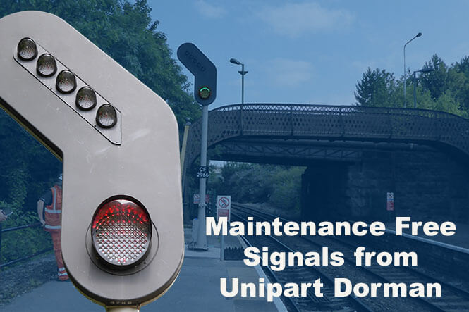
Signals I have looked at closely have had a segment of the lens with a different structure, to make a secondary 'beam' down and to the right, so a driver who is alongside the signal can still read it.
is that still a thing? Not looked recently - since LED's became more prevalent.
LED signals, or Dorman ones at least, have an "eyebrow" of slightly differently angled LEDs to overcome this issue. You can see this in both signals in the image below.
"Reading through" of signals (i.e. ignoring the nearer signal and erroneously reading a more distant one) is a particular hazard, and is well known and acknowledged by scheme designers and signal sighting committees. One additional hazard has arisen with the arrival of LED signals, in that it is better to change over all signals within an area from filament to LED in one go. Otherwise the brighter far-away LED signal may mask a nearer less-bright filament signal. Gradual signal-by-signal upgrading is not favoured - particularly in complex signalling areas.
Was known as the 'hot strip' on a Fresnel lens.Signals I have looked at closely have had a segment of the lens with a different structure, to make a secondary 'beam' down and to the right, so a driver who is alongside the signal can still read it.
is that still a thing? Not looked recently - since LED's became more prevalent.
matchmaker
Established Member
Historically I don't believe the LMS did much in the way of power signaling - there was Mirfield and something on the DC Lines and a few local schemes. The LNER did quite a lot - much of the Great Eastern and York to Newcastle were started before WW2 though I think most of it ended up not being completed until some time after nationalization.
The LMS did a big power installation at Glasgow St Enoch in the 1930s.
edwin_m
Veteran Member
I probably worded my post badly, I was thinking more of line of route rather than local schemes around big stations. The LMS never planned anything on the scale of Liverpool Street to Clacton/Walton or York to Newcastle, which the LNER would have completed if not for WW2. The Southern re-signaled most of its inner areas but the GWR never did more than local schemes such as Paddington and Newport.The LMS did a big power installation at Glasgow St Enoch in the 1930s.
Chris Hamilton
Member
isnt there a problem with 'reading through', where the driver sees not the nearest signal, but the next one?
how do they mitigate that?
Can be a problem, especially on long straights, or where a slight bend in the track can make a signal on another line appear as if it is on yours. Though not a common cause of SPADs, as a well trained driver will know the exact location of every signal on the route, and can usually even identify the location of a blank (failed) signal in the dark and stop short of it (The previous signal should normally have been at danger, but only this week I investigated a signal that had failed only after the driver had passed the previous one, so the driver was confronted with a blank signal).
Also, “Classic” style signal heads (those fitted with filament or led lamps, as opposed to the searchlight style LED light unit), have a bi-focused lens that partially directs the beam at the 5 o’clock position (for a standard LH pole mounted signal, the lens can be rotated to change the focal point for other types of mounting). This is so the driver can see it when right in front of it, as side on it can be difficult to distinguish which aspect is lit if you have stopped close to it. The rest of the beam is focused at a point further back along the track, determined by line speed, curvature and environmental conditions, and every signal has its own Signal Sighting point, agreed by an Engineer whose specific job it is to do it and to continually assess them.
LNW-GW Joint
Veteran Member
Here's an example from Stirling. Causewayhead
The A9 runs parallel to the Alloa-Stirling line. The traffic lights at the road junction have plates (baffles?) fitted which hide the lenses from view of trains.
The new signalling at Liverpool Lime St includes a number of baffles near the platform ends which mask signals from adjacent lines.
The baffles in themselves are sturdy structures requiring concrete foundations!
- Status
- Not open for further replies.