• Our new ticketing site is now live! Using either this or the original site (both powered by TrainSplit) helps support the running of the forum with every ticket purchase! Find out more and ask any questions/give us feedback in this thread!

Signal Boxes and Levers

Status
Not open for further replies.

Andy873

Established Member
Joined
23 Mar 2017
Messages
1,210
I've looked at a few signal box track diagrams and I find them very interesting.

I'm unclear though about several things about them, one box on my old line had 20 levers but was only using 7 at the time of closure in 1964. It was built by the L&Y in 1888 just prior to the building of the carriage shed at Great Harwood.

This box was only opened for movements in / out of the carriage shed and its siding. Due to lack of space around there, this layout really didn't change over the years.

So why have a box with so many spare levers? I understand that removing a set of points would make one lever spare, but why so many spare when you have no space to add extra track etc?

Were these boxes (levers and interlocking frames) supplied with spare capacity? or were they modular, that is built with 10, 15, 20 levers etc? or built specifically for a certain layout / location?

Thanks,
Andy.
 
Sponsor Post - registered members do not see these adverts; click here to register, or click here to log in
R

RailUK Forums

Big Jumby 74

Established Member
Joined
12 Feb 2022
Messages
1,511
Location
UK
Many boxes did have a few spares when built, often due to expected future growth and associated alterations that may have been in the minds of the Railway Companies at the time.
I understand that removing a set of points would make one lever spare
More than one. For any set of points operated from a box, there will have been (at least) one signal, dummy and/or main line signal, possibly also Facing point lock lever (blue) and often things like crossing gate locking. Understand the location you refer to will not likely have had many of these things, albeit I'm not familiar with the area.
 

Snow1964

Established Member
Joined
7 Oct 2019
Messages
8,302
Location
West Wiltshire
Reading the history books gives many examples of early signal boxes that had to be replaced as needed a bigger frame due to extra facilities.

Seems that many of the bigger companies estimated what they might need for next few decades then built standard a series of size boxes. I have seen they labled as type X (where X is a letter).

presumably was cheaper to build standard designs and leave some spare capacity, than to run out of space and have to rebuild a signal box a few years later.

Not sure if it applies to the Ops example, but some frames were secondhand, or more strictly moved from a box that was being replaced. Usually happened where new facility was needed or expansion meant box was in the way and was removed, but equipment had many years of life still in it.
 

Big Jumby 74

Established Member
Joined
12 Feb 2022
Messages
1,511
Location
UK
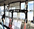
As a follow up, the attached, somewhat poor image, I took at Sandown just before final closure. As you can see, a 'sea' of spare levers! This box had 32 in all, and all were used at one time or other, only No 32, the Up distant which became a fixed distant at some point, being subject to official 'spare' status during the years when the rest of the frame was in full use.

The first real indent in to lever use was on closure of the Newport branch in 1956, 16 levers became redundant, these consisting of: 5 x points, 3 x FPL's, 4 x Dummy shunt signals and 4 x running signals.

Hope that's of some use.

Edit: note the FPL lever (blue) which in this case was No 21 and locked the points (22) coming off the Single line from Shanklin in to the (UP) platform. In general terms any box levers that appear to be cut down in length, are those that had been converted to electric operation, and could be pulled with a couple of fingers. The lever (handle) thickness, as shown here at Sandown, was the norm in my experience and provided a good grip with both hands if needed, but one box I spent a day in had much thinner handles, which I found difficult to get a good grip round, given that in the case concerned it was still old school wires. May be I just have big hands :lol:
 

Attachments

  • BJSandownSB.jpg
    BJSandownSB.jpg
    379.1 KB · Views: 56
Last edited:

Andy873

Established Member
Joined
23 Mar 2017
Messages
1,210
What you all seem t be telling me is that even removing one point can render a few levers spare, maybe there were some extra points at one time or another for the box I mentioned at the beginning.

As you can see, a 'sea' of spare levers!
Yes, the photo tells a story there thanks.

Question please: The word Dummy / Dummy Signal is mentioned a couple of times, what are these?

Thanks.
 

John Webb

Established Member
Joined
5 Jun 2010
Messages
3,506
Location
St Albans
Reading the history books gives many examples of early signal boxes that had to be replaced as needed a bigger frame due to extra facilities.

Seems that many of the bigger companies estimated what they might need for next few decades then built standard a series of size boxes. I have seen they labled as type X (where X is a letter).

presumably was cheaper to build standard designs and leave some spare capacity, than to run out of space and have to rebuild a signal box a few years later......
The 'Type X' descriptions applied widely to signal boxes is a relatively recent invention and comes from the book "The Signal Box - A pictorial history and guide to designs" published in 1986 by Oxford Publishing Company (ISBN 0-86093-224-9) and written by the Signalling Study Group. This Group was formed of members of the Signalling Record Society. They write in their 'Notes for the Reader' that "The 'Type' classifications of signal box designs used in this book is entirely our own invention, and in no case do they represent contemporary terminology." But it has been such a useful way of referring to the style of a box that it's use has become widespread.
 

Big Jumby 74

Established Member
Joined
12 Feb 2022
Messages
1,511
Location
UK
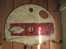
Dummy signal is a ground (position light - in modern parlance) signal. The not quite circular white disc with a red horizontal bar across the centre, which remained horizontal when the signal was 'ON', but when pulled 'OFF' tilted to a 45 degree, bottom left to top right, angle. You may also have seen similar, but painted black with a yellow horizontal bar - these had the same meanings but were usually positioned away from main running lines, such as within 'signalled' areas of goods yards etc.
 

John Webb

Established Member
Joined
5 Jun 2010
Messages
3,506
Location
St Albans
......Question please: The word Dummy / Dummy Signal is mentioned a couple of times, what are these?

Thanks.
These are usually shunting signals of either a small arm or a round disc. There are several nicknames given to them including 'Tommy Dodds'.

== Doublepost prevention - post automatically merged: ==

Dummy signal is a ground (position light - in modern parlance) signal. The not quite circular white disc with a red horizontal bar across the centre, which remained horizontal when the signal was 'ON', but when pulled 'OFF' tilted to a 45 degree, bottom left to top right, angle. You may also have seen similar, but painted black with a yellow horizontal bar - these had the same meanings but were usually positioned away from main running lines, such as within 'signalled' areas of goods yards etc.
Early shunt signals could be a small arm, a 'Half moon' disc as used by the Midland Railway and later the Southern Railway. They could be lower or upper quadrant - the latter a fairly late development which when pulled off went to 45deg top left to bottom right. Such signals could be mounted on posts for better sighting, or to be adjacent to a main arm when a shunt move was required.

The Yellow horizontal bar version was used in specific locations where movements into or out of, for example a headshunt and not onto the main line was required. It allowed the driver to pass the signal (with care) without needing the signalman to continually be operating the shunt signals. They were only cleared to allow a movement onto a running line.
 
Last edited:

Big Jumby 74

Established Member
Joined
12 Feb 2022
Messages
1,511
Location
UK
There are several nicknames given to them including 'Tommy Dodds'.
Ah yes, it is only thanks to input of others on here over time that I got to hear of some of the other nick names. Just that on my wider patch as was, 'Dummy' was the name. Managed to salvage one from one of my old locations, and in true antique etiquette the disc has been left in it's 'patina' (ie semi rust spot blemished) state and is mounted in my office room with it's identity plate below. The (seriously) heavy part is in my garage in grey primer, as it has been for the last 40 years, and still patiently awaits my attention with some black hammerite before reinstating the lenses etc etc!
 

4COR

Member
Joined
30 Jan 2019
Messages
691
You may also have seen similar, but painted black with a yellow horizontal bar - these had the same meanings but were usually positioned away from main running lines, such as within 'signalled' areas of goods yards etc.
A yellow shunt signal has specific meaning - it can be passed when "on" as long as the movement is in a direction where the movement isn't controlled by the signal. Examples of use commonly included headshunts where a train may proceed past the shunt signal when points are set for the headshunt, but the signal must be cleared to (eg) exit onto the mainline.
 

Big Jumby 74

Established Member
Joined
12 Feb 2022
Messages
1,511
Location
UK
Early shunt signals could be a small arm, a 'Half moon' disc as used by the Midland Railway and later the Southern Railway. They could be lower or upper quadrant - the latter a fairly late development which when pulled off went to 45deg top left to bottom right. Such signals could be mounted on posts for better sighting, or to be adjacent to a main arm when a shunt move was required.

The Yellow horizontal bar version was used in specific locations where movements into or out of, for example a headshunt and not onto the main line was required. It allowed the driver to pass the signal (with care) without needing the signalman to continually be operating the shunt signals. They were only cleared to allow a movement onto a running line.
Many thanks for the clarification. I do know of the earlier 'arm' versions through my own researches, but I have a (bad?) habit of only referring to such things as they were in my time on the job, which was of course only a snippet in time as it were, and doesn't give a fuller explanation. So many thanks.
 
Last edited:

Andy873

Established Member
Joined
23 Mar 2017
Messages
1,210
Thanks folks, I get it now - shunt signals etc. I had never heard the name before.

I was sent another signal box diagram a good while ago and this one shows the layout just after the box opened in July 1888. In this diagram the box still had lots of spare levers - 12 in fact.

What I don't know is if the four lanes and the siding were laid before the carriage shed was built a year later, maybe they had only a rough idea of how many levers might be needed?
 

Big Jumby 74

Established Member
Joined
12 Feb 2022
Messages
1,511
Location
UK
A yellow shunt signal has specific meaning
Thank you to both yourself and JW for clarifying. Never had the chance to 'pull' a B/Y as never had any in my areas, so am just going from a faded memory of their existence!
Thanks folks, I get it now - shunt signals etc. I had never heard the name before.

I was sent another signal box diagram a good while ago and this one shows the layout just after the box opened in July 1888. In this diagram the box still had lots of spare levers - 12 in fact.

What I don't know is if the four lanes and the siding were laid before the carriage shed was built a year later, maybe they had only a rough idea of how many levers might be needed?
Are you able to attach the diagram here for comment? Obviously if it's copyright restrictive etc, don't go there.
 

John Webb

Established Member
Joined
5 Jun 2010
Messages
3,506
Location
St Albans
Thanks folks, I get it now - shunt signals etc. I had never heard the name before.

I was sent another signal box diagram a good while ago and this one shows the layout just after the box opened in July 1888. In this diagram the box still had lots of spare levers - 12 in fact.

What I don't know is if the four lanes and the siding were laid before the carriage shed was built a year later, maybe they had only a rough idea of how many levers might be needed?
Very likely. 'My' box was erected in 1892 in anticipation of an expansion from two to four running lines which took place in 1894. A new frame was installed in 1906 when the two goods lines through the station were converted to passenger lines with extra signalling rather than do major alterations to the 1892 frame; the number of levers remained the same. (The MR frames were made of individual castings for each lever position but usually fitted in groups of 4 for convenience.)
 

Andy873

Established Member
Joined
23 Mar 2017
Messages
1,210
Are you able to attach the diagram here for comment? Obviously if it's copyright restrictive etc, don't go there.
Sadly no, it's copyright of the person who drew it.

I can see a set of points in both diagrams (1888 and 1962) which gave access to the carriage siding. The only difference in the 1962 diagram is that it shows another line coming of this siding for the carriage shed at signal 6.

Beyond that, no track is shown due to the fact it's now entering the four lane sidings.

Here is a link to the 1962 diagram (points 12 and signal 6).
 

Big Jumby 74

Established Member
Joined
12 Feb 2022
Messages
1,511
Location
UK
individual castings for each lever position but usually fitted in groups of 4 for convenience
You may be able to answer this with your obviously (to me, if I may say that?) vastly superior knowledge of the detailed stuff. Parts of the Westinghouse 'L' mini lever frame that was victim to my sweaty palms over time, is still in use on a certain preserved line, and another part (consisting of only two levers and the immediate block they are mounted in) also exists as a museum exhibit. I'm presuming then that the L frames, as in 'at lever/just below brass plate' level, were constructed in a series of 'ready to go' sections, so that when being ordered by any Railway Company, Westinghouse would supply 'X' number of these segments ready to be put together on site?
Without consciously thinking about it, I had just presumed the (below brass plate) frame came as a one piece job, designed and built to fit the box in question.

Andy 873 has opened a can of (interesting) worms here :lol::lol:
 

Ken H

Established Member
Joined
11 Nov 2018
Messages
6,615
Location
N Yorks
Some of these white discs with a red line and their power box position light signals are at ground level. But others are on signal gantries often alongside 'proper' signals.
Do these have different names and purpose?
I have seen a position light on a gantry clear and the theatre type route indicator light up with a platform number. But i have never seen a position light clear with a 'feather' type route indicator. Have I not looked hard enough or dont they exist.
Lastly, ddnt some power installations have rotating disc signals rather than position lights. Do they still do that?
 

Islineclear3_1

Established Member
Joined
24 Apr 2014
Messages
6,169
Location
PTSO or platform depending on the weather
The subject of signal boxes is a complex, yet fascinating one

I remember Newhaven Town box; believe it had over 40 levers in its heyday but reduced to just 6 upon rationalisation before a small panel was put in. Certainly a "sea of white levers" there....
 

Andy873

Established Member
Joined
23 Mar 2017
Messages
1,210
Andy 873 has opened a can of (interesting) worms here
Probably!

When I first started to research my old line I wasn't too interested in the signalling side of things, but as time went on I realised just how important signalling is, then and now.

I've tried very hard to understand every little detail about the line, but to really understand it you have to look at other lines and how in general things worked.

That's why a box on the line with so many spare levers intrigues me.
 

Big Jumby 74

Established Member
Joined
12 Feb 2022
Messages
1,511
Location
UK
When I first started to research my old line I wasn't too interested in the signalling side of things, but as time went on I realised just how important signalling is, then and now.
I mean no disrespect to yourself or anyone else, but what you say about the importance of signalling, reflects a comment I had from a gentlemen who was asking me questions on a 'Meet the manager' session at Waterloo one day, many years ago. Can not now remember the detail of his question/complaint, but I do remember that in response to my reply to his initial comments, he retorted..."what has signalling got to do with it....". It was that one comment, that left a mark on my memory of such things, and (perhaps understandably as he was a member of public) I can forgive him.

For anyone who has had experience in the signalling grade, they will tell you (as I mention now) that without signalling, there would not be a railway (as we know it) simple as/end of!

This was recognised back in the 1830's, when procedures (a modern phrase) were put in place to have a competent person (a Constable) walk in front of trains with a flag. Thankfully things have advanced since then, although old habits, as in phrases used within the grade lasted for many years. I myself (and some of my colleagues) still used the phrase 'Bobby' for signaller as did a number of drivers who had occasion to call us up on the SPT's (Signal Post Telephones) from time to time.
 

Andy873

Established Member
Joined
23 Mar 2017
Messages
1,210
I mean no disrespect to yourself or anyone else, but what you say about the importance of signalling, reflects a comment I had from a gentlemen who was asking me questions on a 'Meet the manager' session at Waterloo one day, many years ago. Can not now remember the detail of his question/complaint, but I do remember that in response to my reply to his initial comments, he retorted..."what has signalling got to do with it....". It was that one comment, that left a mark on my memory of such things, and (perhaps understandably as he was a member of public) I can forgive him.

For anyone who has had experience in the signalling grade, they will tell you (as I mention now) that without signalling, there would not be a railway (as we know it) simple as/end of!

This was recognised back in the 1830's, when procedures (a modern phrase) were put in place to have a competent person (a Constable) walk in front of trains with a flag. Thankfully things have advanced since then, although old habits, as in phrases used within the grade lasted for many years. I myself (and some of my colleagues) still used the phrase 'Bobby' for signaller as did a number of drivers who had occasion to call us up on the SPT's (Signal Post Telephones) from time to time.
No disrespect view taken by me at all.

It was my lack of understanding of just how important signalling is. Until I started researching the line my only experience of the railways was finding an excuse for me to travel on a train somewhere, and I never knew there was so much to it all, that is running a railway.
 

edwin_m

Veteran Member
Joined
21 Apr 2013
Messages
26,832
Location
Nottingham
Some of these white discs with a red line and their power box position light signals are at ground level. But others are on signal gantries often alongside 'proper' signals.
Do these have different names and purpose?
I have seen a position light on a gantry clear and the theatre type route indicator light up with a platform number. But i have never seen a position light clear with a 'feather' type route indicator. Have I not looked hard enough or dont they exist.
Lastly, ddnt some power installations have rotating disc signals rather than position lights. Do they still do that?
As with many things to do with signalling, the short answer is "it depends".

Occasionally a free-standing shunting signal would be on a post or even a gantry instead of being on the ground. This was usually when a better view was needed for some reason. But what also happens is that subsidiary signals are combined with main signals, being cleared with the main signal at danger to give various instructions that basically boil down to proceeding but being able to stop short of an obstruction such as another train. When a position light is used for this purpose, then it will only have the two white lights and won't be lit at all except when giving a subsidiary proceed aspect. The various older discs and arms can also be mounted alongside or below main aspects including semaphores.

It used to be allowed for subsidiary aspects to use the route indicator provided for the main signal - feathers as well as theatre indicators I think, though I don't recall ever seeing one. I'm not aware of any area that still has colour lights for main aspects and discs for subsidiary/shunt signals.
 

Taunton

Established Member
Joined
1 Aug 2013
Messages
11,201
My understanding was that the lever frame was the last thing to be designed, the significant item was the locking underneath, with the lever arrangement following on. This could then get tied to standard frame sizes, and also secondhand frames which were kept in stock when others were replaced. The frame and locking may well be a different age (older or newer) than the signal box.

Many railways used signalling contractors rather than do it themselves, and practice varied, as well as railway to railway, between the different contractors. There's a list of who used which contractor here :

 
Last edited:

John Webb

Established Member
Joined
5 Jun 2010
Messages
3,506
Location
St Albans
You may be able to answer this with your obviously (to me, if I may say that?) vastly superior knowledge of the detailed stuff. Parts of the Westinghouse 'L' mini lever frame that was victim to my sweaty palms over time, is still in use on a certain preserved line, and another part (consisting of only two levers and the immediate block they are mounted in) also exists as a museum exhibit. I'm presuming then that the L frames, as in 'at lever/just below brass plate' level, were constructed in a series of 'ready to go' sections, so that when being ordered by any Railway Company, Westinghouse would supply 'X' number of these segments ready to be put together on site?
Without consciously thinking about it, I had just presumed the (below brass plate) frame came as a one piece job, designed and built to fit the box in question.

Andy 873 has opened a can of (interesting) worms here :lol::lol:
Sorry, I am well acquainted with the MR style of lever frame through sheer necessity but know little of anyone else's frames, particularly power frames.
 

Ken H

Established Member
Joined
11 Nov 2018
Messages
6,615
Location
N Yorks
My understanding was that the lever frame was the last thing to be designed, the significant item was the locking underneath, with the lever arrangement following on. This could then get tied to standard frame sizes, and also secondhand frames which were kept in stock when others were replaced. The frame and locking may well be a different age (older or newer) than the signal box.

Many railways used signalling contractors rather than do it themselves, and practice varied, as well as railway to railway, between the different contractors. There's a list of who used which contractor here :
So the design of the frame dictated which lever worked which signal, not ergonomics??
 

Gloster

Established Member
Joined
4 Sep 2020
Messages
10,888
Location
Up the creek
Sorry, I am well acquainted with the MR style of lever frame through sheer necessity but know little of anyone else's frames, particularly power frames.

You may be able to answer this with your obviously (to me, if I may say that?) vastly superior knowledge of the detailed stuff. Parts of the Westinghouse 'L' mini lever frame that was victim to my sweaty palms over time, is still in use on a certain preserved line, and another part (consisting of only two levers and the immediate block they are mounted in) also exists as a museum exhibit. I'm presuming then that the L frames, as in 'at lever/just below brass plate' level, were constructed in a series of 'ready to go' sections, so that when being ordered by any Railway Company, Westinghouse would supply 'X' number of these segments ready to be put together on site?
Without consciously thinking about it, I had just presumed the (below brass plate) frame came as a one piece job, designed and built to fit the box in question.

Andy 873 has opened a can of (interesting) worms here :lol::lol:

There was a very good website on power frames, but I can’t seem to find it: it may have been absorbed into .wbsframe.mste.co.uk (I haven’t had more than a quick look).

It was usual to leave levers that had been taken out of use in place, remove the plate and paint them white. They were usually bolted in position underneath, although it was sometimes necessary to bolt them normal, i.e, with the lever sticking out into the room. I did work in one box where all the redundant levers had been removed and we had an eighty-five lever long frame with about half being in use and the rest spaces. In some places with long frames there might be a gap half-way down so that the signalman could get to the front window, which would probably have an opening frame, and look out. In this case the treads in front of the levers would consist of solid elements, so that there was no slot to jam your toes in.

The various types of signal box, as given by the Signalling Study Group, differentiate between the various standard designs of each railway or contractor as they developed. A particular design, say GWR Type 7, could appear in various lengths, heights, and (occasionally) widths. Although there were bespoke boxes, lengths were often chosen so as to use standard components, such as windows or even full-height panels.

A ground signal could also be known as a Dolly. The difference between naming depended on the area.

One reason for leaving the design of the lever frame until last is because even a quite small change at a late stage could involve quite a lot of redesign or checking. So it is best to leave it until the track layout has been finally confirmed.

Signalmen ran the railway: everybody else acted to our direction.
 

Taunton

Established Member
Joined
1 Aug 2013
Messages
11,201
. I'm not aware of any area that still has colour lights for main aspects and discs for subsidiary/shunt signals.
I always thought of that as a Southern Region thing. Each region tended to bring forward the practices of their forebear companies, so there were differences. Southern discs also seemed a different shape, not completely circular. G M Kichenside, one of Ian Allan's magazine editors in the 1960s-70s, and a signal engineer by background, did a whole book on it all, with all the differences, which became a standard and is often sold secondhand.

It is surprising how much 4-aspect colour light signalling was in earlier installations controlled from traditional local signalboxes with manual points worked by levers, and I believe the WCML at Stockport, among others, still is.
 

edwin_m

Veteran Member
Joined
21 Apr 2013
Messages
26,832
Location
Nottingham
It is surprising how much 4-aspect colour light signalling was in earlier installations controlled from traditional local signalboxes with manual points worked by levers, and I believe the WCML at Stockport, among others, still is.
Stockport does indeed still have levers, but I believe all the points are power-worked and all signals are colour lights.
 

Big Jumby 74

Established Member
Joined
12 Feb 2022
Messages
1,511
Location
UK
There was a very good website on power frames, but I can’t seem to find it: it may have been absorbed into .wbsframe.mste.co.uk (I haven’t had more than a quick look).
The wbsframe site is highly recommended (by me!). I believe one of those who is a leading figure of same, was an acquaintance of a colleague of mine back then.

I'm not aware of any area that still has colour lights for main aspects and discs for subsidiary/shunt signals.
I always thought of that as a Southern Region thing
We still had old school dummies, gantry mounted, working in conjunction with main colour light aspects and route indicators at Waterloo in the late 70's, although I can not recall when they were replaced? Here's my example, (EDIT: not from Waterloo) to give an idea of the shape of some of the the things! I think Waterloo's gantry mounted dummies, were in their last guise, of a circular nature. Ignore the vertical light patch, just the sun shining past the edge of the window blind.
 

Attachments

  • BJ-BR(S) style ground dummy.JPG
    BJ-BR(S) style ground dummy.JPG
    1.9 MB · Views: 8
Last edited:

edwin_m

Veteran Member
Joined
21 Apr 2013
Messages
26,832
Location
Nottingham
We still had old school dummies, gantry mounted, working in conjunction with main colour light aspects and route indicators at Waterloo in the late 70's, although I can not recall when they were replaced? Here's my example, to give an idea of the shape of the things! Ignore the vertical light patch, just the sun shining past the edge of the window blind.
The box at Waterloo survived up until the late 1980s when replaced by the power box at Wimbledon - the last big scheme to rely entirely on relays.
 
Status
Not open for further replies.

Top