• Our booking engine at tickets.railforums.co.uk (powered by TrainSplit) helps support the running of the forum with every ticket purchase! Find out more and ask any questions/give us feedback in this thread!

Victoria & south london resignalling phase 5: what actually changes on the ground?

BRX

Established Member
Joined
20 Oct 2008
Messages
3,640
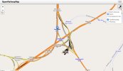
Screenshot 2024-04-11 at 18.03.39.jpg

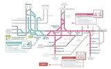
Above is a map of this phase, taken from the NR website here.

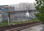
I'm currently noticing new signal gantries going up here and there.

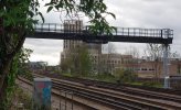
For example the one in the photo below, just wet of Denmark Hill station.

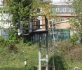
Screenshot 2024-04-11 at 18.07.29.jpg

This is close to but not in an identical location to, an existing gantry, shown in the photo below (this is looking in the other direction along the same stretch of line:


Screenshot 2024-04-11 at 18.08.43.jpg


My main question is why is there a new gantry in a slightly different location? Is it just because the old one needs renewing and it's easier to put up a new one in a separate operation from taking down the old one?

Or does the new location improve things signalling wise - for example are there places where they are trying to increase the number of track sections?

Does the resignalling involve any significant changes to the signalling layout on the ground, or is it pretty much all like-for-like, but with newer equipment and control from a different location?
 
Last edited:
Sponsor Post - registered members do not see these adverts; click here to register, or click here to log in
R

RailUK Forums

Tim M

Member
Joined
9 Jul 2016
Messages
184
The Victoria Area Resignalling Scheme (VARS) retained a number of signal structures from previous installations. They would have been 40 plus years old in the early 1980’s so 80 years old today and life expired. That may be the reason for replacements being installed. It’s also possible that recalculating braking distances and headway requirements for current day trains with improved performance may indicate changes to signal spacing plus siting and sighting issues resulting in new signal structures.

VARS was a great project to work on with excellent teamwork between the customer (BR S&T at Croydon anbd Battersea) and supplier (GEC-General Signal at Borehamwood, my employer).
 

BRX

Established Member
Joined
20 Oct 2008
Messages
3,640
The older gantry in my photo, I'd wondered if it might be a structure left over or re-used from the overhead electrification that used to exist on this line, but looking more carefully it's probably not quite that old and doesn't match old photos of the overhead wiring gantries.
 

Bald Rick

Veteran Member
Joined
28 Sep 2010
Messages
29,221
New gantry positons are often to enable better sighting of signals, and/or to have better compliance with braking distances etc.

paging @MarkyT who will have much expertise in this subject.
 

BRX

Established Member
Joined
20 Oct 2008
Messages
3,640
That particular one, they rarely stop westbound freight trains at, and I've always assumed one of the reasons is that if they do, it's effectively stopped at the bottom of a hill and a heavy train will take quite a while to get going again (on a stretch with a fairly busy passenger service to fit between). The new location would seem to just make this issue greater...as an even greater portion of the train would be stopped on an upwards incline. But maybe an increased sighting distance after you emerge from under the denmark hill bridge means it can be approached at a greater speed? This is all just my ill-informed speculation though; it would be interesting to know the actual reasoning.
 

Railsigns

Established Member
Joined
15 Feb 2010
Messages
2,504
The gantry is being renewed primarily because of its condition, but it's being moved to a new position 96 metres further west for better signal spacing.
 

Belperpete

Established Member
Joined
17 Aug 2018
Messages
1,650
VARS was a great project to work on with excellent teamwork between the customer (BR S&T at Croydon anbd Battersea) and supplier (GEC-General Signal at Borehamwood, my employer).
I was told that the Southern fought touth and nail for Westinghouse to get the contract, as they wanted consistent equipment and designs for the Brighton line, but under BR's "allocated contracts" agreement it was GEC's turn for a big contract.
 

BRX

Established Member
Joined
20 Oct 2008
Messages
3,640
The gantry is being renewed primarily because of its condition, but it's being moved to a new position 96 metres further west for better signal spacing.
Thanks. There's no fundamental change to the signalling layout then, just an adjustment of the position?
 

BRX

Established Member
Joined
20 Oct 2008
Messages
3,640
Two more questions... what does "Relock" mean on the NR map?
And the earliest the new system will get switched on is 2025, is that right?
 

Belperpete

Established Member
Joined
17 Aug 2018
Messages
1,650
The Victoria Area Resignalling Scheme (VARS) retained a number of signal structures from previous installations.
The VARS scheme was a real scrimp and save job - anything that didn't need to be replaced wasn't. I had never seen a scheme plan like it, every single piece of equipment seemed to have a different symbol against it defining what was and wasn't being reused. So a post or gantry might be reused as-is, modified or replaced, the head might be reused or replaced, ditto the route indicator, etc etc.

Two more questions... what does "Relock" mean on the NR map?
A relock is where the interlocking is replaced, but the trackside control equipment and cabling aren't. The term relock took off when the early computer based interlockings started being replaced by later models, without affecting any of the trackside control equipment. However, it also applies where a life-expired relay interlocking is replaced with a computer based interlocking that interfaces to the existing relay-based trackside control equipment.

The wiring used in some 1970s relay interlockings was starting to show its age, while that in the trackside equipment cupboards was still perfectly serviceable, for example.
A relock allows you to have a replacement interlocking without going to the expense of changing all the trackside cabling and equipment cupboards.
 
Last edited:

Bald Rick

Veteran Member
Joined
28 Sep 2010
Messages
29,221
The wiring used in some 1970s relay interlockings was starting to show its age, while that in the trackside equipment cupboards was still perfectly serviceable, for example.
A relock allows you to have a replacement interlocking without going to the expense of changing all the trackside cabling and equipment cupboards.

To add to this (and havig been in the relay room at Victoria ASC more times than i care to remember), the old relay interlockings are massive. The relay room at Victoria ASC, which only had the interlockings that controlled the first few miles out of Victoria, is the size of a mid size ‘metro’ supermarket. The interlockings that replaced them are the size of a couple of fridge freezers.
 

Sad Sprinter

Established Member
Joined
5 Jun 2017
Messages
1,829
Location
Way on down South London town
The Victoria Area Resignalling Scheme (VARS) retained a number of signal structures from previous installations. They would have been 40 plus years old in the early 1980’s so 80 years old today and life expired. That may be the reason for replacements being installed. It’s also possible that recalculating braking distances and headway requirements for current day trains with improved performance may indicate changes to signal spacing plus siting and sighting issues resulting in new signal structures.

VARS was a great project to work on with excellent teamwork between the customer (BR S&T at Croydon anbd Battersea) and supplier (GEC-General Signal at Borehamwood, my employer).

Perhaps you can tell me, why is VC and VS located at Clapham Junction?
 

Tim M

Member
Joined
9 Jul 2016
Messages
184
The VARS scheme was a real scrimp and save job - anything that didn't need to be replaced wasn't. I had never seen a scheme plan like it, every single piece of equipment seemed to have a different symbol against it defining what was and wasn't being reused. So a post or gantry might be reused as-is, modified or replaced, the head might be reused or replaced, ditto the route indicator, etc etc.
Quite a few of the scheme plans I had got wet during location case surveys! I walked most of the scheme twice. I don’t remember old signal heads etc. being kept, it’s possible some predated the use of SL35 lamps as installed pre-war so incompatible with 1970’s standards.

BR had already replaced Tulse Hill (?) and Crystal Palace with free wired interlockings and trackside loc‘s etc, GEC added some non-vital Reed and TDM equipment. Some of the BR people involved in that work had also been involved in FR signalling works, small world.

I can understand your earlier comment about Croydon preferring Westinghouse as a follow on from the successful London Bridge job. It probably helped that the GEC Project Engineer had Southern experience at Faversham, transferring with several of us from the Edinburgh and East of Scotland job, another allocated Contract.

What probably annoyed both GEC and Westinghouse was the award of the Waterloo Area Resignalling to ML of Plymouth, I nearly moved to the far west and such was ML’s confidence that I would join them they put my name forward for a track access pass, I went to Chippenham instead.

Perhaps you can tell me, why is VC and VS located at Clapham Junction?
Availability of railway land for the size of building involved. Both VC and VS panels were 70 feet long, add to that the space required for panel interface relays (predating panel processing in the back of the panels), Train Describer and Telecoms Room plus two interlocking rooms, there was no space available at Victoria. Note the two relay rooms had to be double stacked at Victoria, space was that tight. Images from the GEC brochure, a few signalmen plus a mix of BR S&T plus GEC staff as only a couple of areas had been commissioned at that stage.

I ask this every now and then: where is 'Stewart Lane'?
Extract from Open Railway Map on line.
 

Attachments

  • IMG_0140.jpeg
    IMG_0140.jpeg
    503.6 KB · Views: 183
  • IMG_0141.jpeg
    IMG_0141.jpeg
    514.1 KB · Views: 183
  • IMG_0142.jpeg
    IMG_0142.jpeg
    365.8 KB · Views: 179
Last edited:

Sad Sprinter

Established Member
Joined
5 Jun 2017
Messages
1,829
Location
Way on down South London town
Quite a few of the scheme plans I had got wet during location case surveys! I walked most of the scheme twice. I don’t remember old signal heads etc. being kept, it’s possible some predated the use of SL35 lamps as installed pre-war so incompatible with 1970’s standards.

BR had already replaced Tulse Hill (?) and Crystal Palace with free wired interlockings and trackside loc‘s etc, GEC added some non-vital Reed and TDM equipment. Some of the BR people involved in that work had also been involved in FR signalling works, small world.

I can understand your earlier comment about Croydon preferring Westinghouse as a follow on from the successful London Bridge job. It probably helped that the GEC Project Engineer had Southern experience at Faversham, transferring with several of us from the Edinburgh and East of Scotland job, another allocated Contract.

What probably annoyed both GEC and Westinghouse was the award of the Waterloo Area Resignalling to ML of Plymouth, I nearly moved to the far west and such was ML’s confidence that I would join them they put my name forward for a track access pass, I went to Chippenham instead.


Availability of railway land for the size of building involved. Both VC and VS panels were 70 feet long, add to that the space required for panel interface relays (predating panel processing in the back of the panels), Train Describer and Telecoms Room plus two interlocking rooms, there was no space available at Victoria. Note the two relay rooms had to be double stacked at Victoria, space was that tight. Images from the GEC brochure, a few signalmen plus a mix of BR S&T plus GEC staff as only a couple of areas had been commissioned at that stage.


Extract from Open Railway Map on line.

Thanks, amazing pictures. All done with British firms and technology too at the time. The future was yesterday.

"Three Bridges ROC" just isn't the same.
 

Recessio

Member
Joined
4 Aug 2019
Messages
667
To add to this (and havig been in the relay room at Victoria ASC more times than i care to remember), the old relay interlockings are massive. The relay room at Victoria ASC, which only had the interlockings that controlled the first few miles out of Victoria, is the size of a mid size ‘metro’ supermarket. The interlockings that replaced them are the size of a couple of fridge freezers.
That's always the way with old electronics. In a non railway job I was involved with, we replaced three entire floors worth of 1960s-1980s era Westinghouse and Ealing electronics racks, with two servers about the size of a filing cabinet each.

I wonder if the space the railway saves could be repurpose for anything useful? (we ended up using it as storage space, seems a bit of a waste)
 

MarkyT

Established Member
Joined
20 May 2012
Messages
6,263
Location
Torbay
The wiring used in some 1970s relay interlockings was starting to show its age, while that in the trackside equipment cupboards was still perfectly serviceable, for example.
A relock allows you to have a replacement interlocking without going to the expense of changing all the trackside cabling and equipment cupboards.
Once the insulation degradation sets in, the risk in interlockings can also be higher, especially big complex ones like Victoria where wires are packed tightly in the ducting. Pulling old wires out when doing alterations or piecemeal renewals can be dicy, hence many relay rooms have harsh restrictions on what work may be carried out. Some rooms had less than optimal design choices in racking & ducting layouts where wires were subject to greater stresses than other sites. 'Free wired' interlockings had the most and lengthiest wiring in the ducts; in theory wires could stretch from one end of a big room to the other. Geographical was more modular, using multicore cables between units, but often with a lot of supplementary free wiring. The WR E10K interlockings were a compromise. Although free wired within each individual rack, where circuits needed to go across to another rack they used a structured system of inter-rack multicore cabling terminated on the rack top 'belling lees' (manufacturer of the usual screw terminal blocks used). So the Western interlockings had less individual wire but more termination points on average per circuit. That didn't seem to be a reliability issue in service, a concern some full free wiring enthusiasts had about the method.
 

contrex

Member
Joined
19 May 2009
Messages
878
Location
St Werburghs, Bristol
Extract from Open Railway Map on line.
Sorry, I was not as clear as I could have been. I know exactly where Stewarts Lane is (with a 's'), and have done for over 60 years. I was, I suppose clumsily, trying to draw attention to the label 'Stewart Lane Interlocking' (without an 's') which I could see on the National Rail diagram reproduced at the start of this thread. It seem to come up from time to time.
 

BRX

Established Member
Joined
20 Oct 2008
Messages
3,640
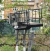
Noticed today, one of the other new gantries along that section near Denmark hill, a cantilevered one, is visibly wonky, with the horizontal part taking on a twist along its length.
(photos below)

Screenshot 2024-04-12 at 16.09.48.jpgScreenshot 2024-04-12 at 16.10.20.jpg
 

Tim M

Member
Joined
9 Jul 2016
Messages
184
Sorry, I was not as clear as I could have been. I know exactly where Stewarts Lane is (with a 's'), and have done for over 60 years. I was, I suppose clumsily, trying to draw attention to the label 'Stewart Lane Interlocking' (without an 's') which I could see on the National Rail diagram reproduced at the start of this thread. It seem to come up from time to time.
Alongside and just to the west of Linford Strret Junction sees the Eurostar chord towards Waterloo. If you can zoom in to Google Earth in 3D you should be able to find it. Another way of describing it is where the Chatham Line is on the viaduct, the Relay Room is on the level of the line at ground level just before the trailing connections from Stewart’s Lane yard.
 

ComUtoR

Established Member
Joined
13 Dec 2013
Messages
9,470
Location
UK
Sorry, I was not as clear as I could have been. I know exactly where Stewarts Lane is (with an 's'), and have done for over 60 years. I was, I suppose clumsily, trying to draw attention to the label 'Stewart Lane Interlocking' (without an 's') which I could see on the National Rail diagram reproduced at the start of this thread. It seems to come up from time to time.

Probably a typo but I wanted to be absolutely sure. I have amended you're errors and hope that others can see how important it is to be correct when you are trying to be 'That Person'

1712946869564.png

For absolute clarity I have attached a diagram where the 'Up and Down' Stewarts Lane are clearly marked. I hope that helps with your enquiry.
 

Nicholas Lewis

Established Member
Joined
9 Aug 2019
Messages
6,139
Location
Surrey
The Victoria Area Resignalling Scheme (VARS) retained a number of signal structures from previous installations. They would have been 40 plus years old in the early 1980’s so 80 years old today and life expired. That may be the reason for replacements being installed. It’s also possible that recalculating braking distances and headway requirements for current day trains with improved performance may indicate changes to signal spacing plus siting and sighting issues resulting in new signal structures.

VARS was a great project to work on with excellent teamwork between the customer (BR S&T at Croydon anbd Battersea) and supplier (GEC-General Signal at Borehamwood, my employer).
My first industry placement was at Borehamwood in 1980 spent most of it in the drawing office doing the designs for the emergency override routes for the VC relay rooms except Victoria Central although not sure my stenciling skills were really up to scratch! Got to help out in a very junior capacity during commissioning of Stewarts Lane interlocking that was a whole different way of doing commissioning's compared to today.
 

Belperpete

Established Member
Joined
17 Aug 2018
Messages
1,650
Quite a few of the scheme plans I had got wet during location case surveys! I walked most of the scheme twice. I don’t remember old signal heads etc. being kept, it’s possible some predated the use of SL35 lamps as installed pre-war so incompatible with 1970’s standards.
There were a number of signal heads that had already been replaced by maintenance with SL35 heads, and it was deemed didn't need replacing.

The WARS scheme gained the nickname "Wimberloo", because of the number of times the potential site for the control centre was changed during scheme development.

As I recall the building at Clapham Junction included rooms for both the SW and Central side relay rooms. Both massive rooms However, it was decided for railway political reasons that they had to go in separate buildings. The spare room got nicknamed the football pitch as I recall. Something to do with Clapham Junction being a SW station, and they didn't want the Central RR being maintained by SW technicians.

The WR E10K interlockings were a compromise. Although free wired within each individual rack, where circuits needed to go across to another rack they used a structured system of inter-rack multicore cabling terminated on the rack top 'belling lees' (manufacturer of the usual screw terminal blocks used). So the Western interlockings had less individual wire but more termination points on average per circuit. That didn't seem to be a reliability issue in service, a concern some full free wiring enthusiasts had about the method.
The problem with E10k from a design point of view was that every time a circuit went from one rack to another, you had to find a spare allocation in the rack-rack multi cores to run it in. And you had to show it on the circuit diagram between the contacts, which meant you had to leave more space between those contacts (or rub out everything to the right and redraw it if you hadn't). With alterations, they were usually reluctant to put in more rack-rack multicores, particularly just for one connection. So if your circuit ran from rack A to rack B, but there were no spare cores left in the A-B multicore, you might have to go A-C then C-B.

The advantage of it though was that they could replace an individual rack relatively easily. Build the new rack, undo the multicores from the top of the old rack, remove the old and put in the new, and reterminate the multicores. When I moved to Reading, I was astounded to find that when the Area installation teams had nothing much to do, they were tasked with routine relay rack replacements.
 
Last edited:

ComUtoR

Established Member
Joined
13 Dec 2013
Messages
9,470
Location
UK
Unless of course, it was deliberate <D

Keeping on topic. That map shows 'Battersea Yard' and not Stewarts Lane Depot. Is there an official title of the depot ? The sectional Appendix states Stewarts Lane Depot.
 

MarkyT

Established Member
Joined
20 May 2012
Messages
6,263
Location
Torbay
The problem with E10k from a design point of view was that every time a circuit went from one rack to another, you had to find a spare allocation in the rack-rack multi cores to run it in. And you had to show it on the circuit diagram between the contacts, which meant you had to leave more space between those contacts (or rub out everything to the right and redraw it if you hadn't). With alterations, they were usually reluctant to put in more rack-rack multicores, particularly just for one connection. So if your circuit ran from rack A to rack B, but there were no spare cores left in the A-B multicore, you might have to go A-C then C-B.
CAD, with its ability to move elements around on a circuit drawing more easily for such alterations, came a bit late for much use in the relay interlocking field. I found a few awfully convoluted circuit routings in some of the Welsh interlockings I worked on at Reading in the mid-1980s.
The advantage of it though was that they could replace an individual rack relatively easily. Build the new rack, undo the multicores from the top of the old rack, remove the old and put in the new, and reterminate the multicores. When I moved to Reading, I was astounded to find that when the Area installation teams had nothing much to do, they were tasked with routine relay rack replacements.
The technique also allowed new racks to be designed, prewired, and partially tested in advance for larger alterations, as at Stoke Gifford for the Royal Mail terminal job in the 1990s.
 

godfreycomplex

Established Member
Joined
23 Jun 2016
Messages
1,304
Unless of course, it was deliberate <D

Keeping on topic. That map shows 'Battersea Yard' and not Stewarts Lane Depot. Is there an official title of the depot ? The sectional Appendix states Stewarts Lane Depot.
Two separate places, Battersea Yard is the technical designation for the two so called “Under Bank” sidings next to the dogs home (which was built on the rest of the former yard)
 

LBMPSB

Member
Joined
20 Apr 2019
Messages
126
The gantry is being renewed primarily because of its condition, but it's being moved to a new position 96 metres further west for better signal spacing.
And possibly because the overlaps are non standard in the old signalling and moving signals back aloows overlaps to become standard.

Unless of course, it was deliberate <D

Keeping on topic. That map shows 'Battersea Yard' and not Stewarts Lane Depot. Is there an official title of the depot ? The sectional Appendix states Stewarts Lane Depot.
Probably Project designers license. We had this occur with the Resignalling, recontrol of London Bridge ASC to Three Bridges ROC. Very confusing for Drivers and SIgnallers when lines are known as one thing for decades and someone decides it needs a new name. E.G. Someone decided after all the years since the lines from Lee to the sidings at Bramdene wear laid, were called Up & Down Lee Spur lines, they would rename them Up & Down Hither Green Spur lines! Why? Because they can!
 
Last edited:

Top