Do we know if there is point to point locking between points 105 and 106?
Sorry, don't know. Standard double junction flank protection controls in the route and signal layers will be present no doubt. At some date, I think designers were instructed to stop putting direct point-to-point locking in relay and processor interlockings. Back in mechanical days, it was standard as it simplified the locking significantly.
Questions (I not looking for answers, just things to think about, the kinds of questions that the investigators will be asking, so please don’t speculate here):
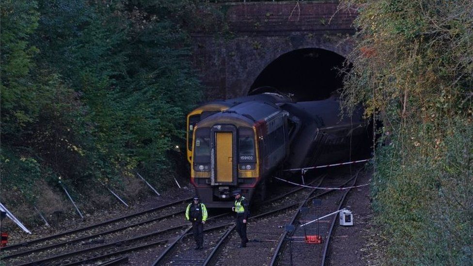
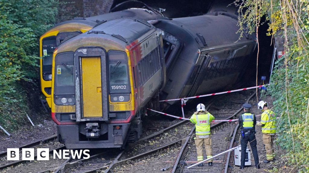
What was the reason that caused the driver of GWR train 1F30 to stop their train where they did? Did it actually hit something? Was there a problem with the points fittings (point number 106) ? Or was there a problem with the train? If this train did hit something or if there was a problem with 106 points, did this train derail?
Certainly an odd place to stop voluntarily, so suggests some problem forced a halt.
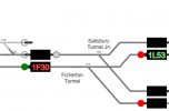
Why did the TD not step the ‘head code’ forward for 1L53 when the train has clearly passed signal SY31?
Good question. Depending on the system and how its wired, that's one of the things signallers, techs, managers and investigators often look at after an incident as a quick indicator as to whether a SPAD has occurred. Some, but not all TDs require that the route is set for a track circuit triggered step to take place. There should also be comprehensive logging data available from the interlocking.
If there was no problem with GWR train 1F30 operating the track circuits (where it is in the photos I would expect it to be on at least two track circuits) the interlocking should have held signal SY31 at red. So was there a problem with the track circuits?
In the photos, points 105 look to be lying reverse, as they would have been needed for the move of 1F27 over the junction. This is the opposite way to that required for 1L53 if there is point to point locking between points 105 and 106. We don’t know which way points 106 are because we can’t see them and they may be under the GWR train. If there is point to point locking, then if points 105 are not set correctly, signal SY31 should not clear. Was there a problem here?
Even if there's no direct point-to-point locking incorporated, there will definitely be standard flank protection controls that require 105 aligned towards Andover before SY31 can clear.
Did the signaller route signal SY31? If the answer is no, then signal SY31 should not clear to a proceed aspect. Did signal SY31 stay red? Was it lit? What was the sighting like? Could approaching train drives see it clearly and at the required minimum distance?
If SY31 does not show an proceed aspect or if the signal is not illuminated , then the AWS should result in the AWS horn sounding in the leading cab of train 1L53. Was the track and lineside equipment for the AWS working? Was the train AWS equipment working?
SY31 should be fitted with TPWS equipment. The TPWS transmitter loops should be energised at all times unless the signal is showing a proceed aspect. Was the track and lineside equipment for the TPWS working? Was the train TPWS equipment working?
Definitely fitted. Can be seen on Google Earth images. Overspeed loops approx 200m from signal, with the AWS ramp nearby. Note the distance from signal to junction clearance point is approx 160m which is usually considered an acceptable overlap distance for the 50mph approach speed.
The signal, SY31 requires electricity to work, as does the TPWS. Was there a loss of power to this equipment, causing SY31 to go ‘black’ and disappear into the darkness? The signal identification plate/sign should be made of the reflective type so that it can be seen more easily in poor light conditions. Was it? Was it clean?
The AWS, thankfully, will continue to work through a signalling power failure, giving a cautionary indication and imposing a braking intervention if not acknowledged.