• Our booking engine at tickets.railforums.co.uk (powered by TrainSplit) helps support the running of the forum with every ticket purchase! Find out more and ask any questions/give us feedback in this thread!

Great Western Electrification Progress

Status
Not open for further replies.

GRALISTAIR

Established Member
Joined
11 Apr 2012
Messages
7,909
Location
Dalton GA USA & Preston Lancs
Further to the historical remarks above, there was a lot of concern at the time that WCML north from Weaver Junction was not authorised in time to be a smooth follow-on to the southern half. Manchester and Liverpool to London were completed in 1966 and the Birmingham area in 1967, but Weaver Junction northwards was not authorised until 1970. The time gap seems small when seen from this distance but it seemed a big matter at the time.

It meant double-headed class 50s taking over from the electric at Crewe. Fun times and I remember them well. :D
 
Sponsor Post - registered members do not see these adverts; click here to register, or click here to log in
R

RailUK Forums

jimm

Established Member
Joined
6 Apr 2012
Messages
5,231
Why Dundas Aqueduct? This explanation came from another poster on 15th July.

"The work at Dundas Aqueduct is actually widening to accommodate the Class 165s. I wonder if work needs to be done at Avoncliff too?"

So I can understand that. However it's not strictly electrification work is it? I mean, if another not so wide (or is it length in respect of Avoncliff?) unit had been re-allocated, then it would not have been needed.

Are we sure it isn't just to ensure a level track when it meets the lowered junction at Bathampton?

But unless Network Rail is having one of its hazier moments over doing work at the aqueduct, I would guess the work they are doing now will also provide extra vertical clearance for potential future wiring, as well as the lateral clearance needed for Turbos to fit through the arches, thus avoiding the need for a return visit should electrification be approved at some point. Does anyone know if this is the case?
 

GRALISTAIR

Established Member
Joined
11 Apr 2012
Messages
7,909
Location
Dalton GA USA & Preston Lancs
But unless Network Rail is having one of its hazier moments over doing work at the aqueduct, I would guess the work they are doing now will also provide extra vertical clearance for potential future wiring, as well as the lateral clearance needed for Turbos to fit through the arches, thus avoiding the need for a return visit should electrification be approved at some point. Does anyone know if this is the case?

According to the twitter feed (@networkrailgwrm) - "The work is to allow the line to be used as diversionary route for freight trains."

These two statements are of course NOT mutually exclusive.
 

swt_passenger

Veteran Member
Joined
7 Apr 2010
Messages
31,493
The wording in a recent PR piece was:

On Saturday, 1 August we will start the track lowering work at Dundas Aqueduct. We have collaborated closely with Bath and North East Somerset Council, Wiltshire Council and Historic England in order to make sure that our work will protect this ancient monument. We need to lower approximately 1 mile of track to allow the line to be used as a diversionary route for freight trains in the future. It will also mean that we have the right capacity for the DMUs (diesel shuttle trains) that will be cascaded from the Thames Valley area once the electrification project is complete – this will give an increased passenger capacity on the valley line for local commuters.

http://www.networkrail.co.uk/Newsletter-TPOD-week-2.pdf
The likelihood is they are taking advantage of the closure to do other work that would otherwise require a separate closure.

Situation normal as far as I can see - as we know, gauge clearance for 165/166 DMUs in the west is an approved part of the CP5 outputs, although a separate project to the electrification. But it's swings and roundabouts; electrification elsewhere is what makes the Turbos available, after all.

Freight gauge clearance is a separate question, but it would be nonsensical to undergo a third closure, even if the work here cannot be used initially.
 
Last edited:

LNW-GW Joint

Veteran Member
Joined
22 Feb 2011
Messages
19,739
Location
Mold, Clwyd
According to the twitter feed (@networkrailgwrm) - "The work is to allow the line to be used as diversionary route for freight trains."

W12 clearance then. Must be part of the route expansion from Southampton Docks.
I was surprised recently to follow the route of a Wentloog (Cardiff)-Southampton container train, and it ran the full length of the GWML to Reading before heading south.
Clearing the Westbury route for full-height containers means they can stay clear of the GWML.
 

swt_passenger

Veteran Member
Joined
7 Apr 2010
Messages
31,493
W12 clearance then. Must be part of the route expansion from Southampton Docks.

There is no sign of a freight gauge project for the overall route. (As of the March CP5 enhancements update this year; unless they have sneaked it in as an extra since.)

There is a Southampton to Basingstoke W12 clearance project outstanding, to improve upon the W10 project completed in CP4, but no mention of the route via Westbury.
 

Hophead

Established Member
Joined
5 Apr 2013
Messages
1,193
A couple of photos taken on Saturday from the Thames Path bridge at Tilehurst.

The view west shows not just a dropper, but also a pair of registration arms. Arms have appeared on quite a few droppers on the section from Tilehurst to just past Cholsey. I wouldn't expect wires for a while yet, though: as you can see, there are droppers without arms, gantries without droppers, masts without gantries (or gantries incomplete), as well as bases without masts (you can see one bottom left in the view east towards Tilehurst Station). Furthermore, there seems to have been little work at the stations themselves (so far as I could tell from brief station stops). Goring does have a bit of digging going on, so maybe a mast or two will appear before the summer is out.

[Here's hoping I've attached successfully! :roll:]
 

Attachments

  • TilehurstEast.jpg
    TilehurstEast.jpg
    125.8 KB · Views: 151
  • TilehurstWest.jpg
    TilehurstWest.jpg
    125.6 KB · Views: 154

edwin_m

Veteran Member
Joined
21 Apr 2013
Messages
24,971
Location
Nottingham
There is no sign of a freight gauge project for the overall route. (As of the March CP5 enhancements update this year; unless they have sneaked it in as an extra since.)

There is a Southampton to Basingstoke W12 clearance project outstanding, to improve upon the W10 project completed in CP4, but no mention of the route via Westbury.

Still, if they have to do something to clear 165s it would be very short-sighted not to allow for W12 as well, unless the costs of doing that were hugely greater.

I seem to recall Southampton to Basingstoke via the Laverstock Curve is being (or has been) cleared as an alternative W12 route towards Reading, so that would only leave Laverstock to Bathampton although that does include at least two tunnels. I don't think there's much freight between Southampton and Cardiff but opening up another route to the Midlands via Bristol and Cheltenham would be useful.
 

Bald Rick

Veteran Member
Joined
28 Sep 2010
Messages
29,229
A couple of photos taken on Saturday from the Thames Path bridge at Tilehurst.

The view west shows not just a dropper, but also a pair of registration arms. Arms have appeared on quite a few droppers on the section from Tilehurst to just past Cholsey. I wouldn't expect wires for a while yet, though: as you can see, there are droppers without arms, gantries without droppers, masts without gantries (or gantries incomplete), as well as bases without masts (you can see one bottom left in the view east towards Tilehurst Station). Furthermore, there seems to have been little work at the stations themselves (so far as I could tell from brief station stops). Goring does have a bit of digging going on, so maybe a mast or two will appear before the summer is out.

[Here's hoping I've attached successfully! :roll:]


I don't wish to be pedantic, but droppers are the small pieces of wire that connect the catenary (top) wire to the contact (bottom) wire every 10 metres or so.

I think what you mean by 'dropper' is the small part steelwork (SPS). Sometimes known as downpipes.
 

Hophead

Established Member
Joined
5 Apr 2013
Messages
1,193
I don't wish to be pedantic, but droppers are the small pieces of wire that connect the catenary (top) wire to the contact (bottom) wire every 10 metres or so.

I think what you mean by 'dropper' is the small part steelwork (SPS). Sometimes known as downpipes.

That was what I meant - noted (if I remember) in case I'm out that way again with a camera before it's all complete (chances are high and I'm not in the Thames Valley often).

Thanks
 

swt_passenger

Veteran Member
Joined
7 Apr 2010
Messages
31,493
Still, if they have to do something to clear 165s it would be very short-sighted not to allow for W12 as well, unless the costs of doing that were hugely greater.
That's how I see it. The wiring closure allows the Turbo gauge clearance to be done in parallel, and that is the work that is needed now. Then adding W10 and electrification is then fairly easy to add on.
I seem to recall Southampton to Basingstoke via the Laverstock Curve is being (or has been) cleared as an alternative W12 route towards Reading...

That's what I just posted, based on what's in the CP5 plan, although I should have said 'under way' rather than outstanding. W12 from W10 is all to do with marginal width increases, rather than height, so I'd assume isn't such a large amount of work.
 

33Hz

Member
Joined
2 Dec 2010
Messages
513
This week I had the opportunity to drive along the GWML past Goring and Pangbourne and then an hour or so later compare it with the last major electrification project, HS1.

I didn't spot any "70 foot high" masts on the GWML but I was pleasantly surprised to see a lot of steelwork in place. There was nothing higher than a bridge parapet along that section of the route that I could spot. Yes, it is very shiny but as others have pointed out, it will weather in.

Comparing it with HS1 as seen from the M20, the masts there are significantly higher with the additional height being used to carry the return wire. They have weathered in significantly in the twelve years they have been installed, generally not standing out that significantly in the landscape.
 

AM9

Veteran Member
Joined
13 May 2014
Messages
14,286
Location
St Albans
This week I had the opportunity to drive along the GWML past Goring and Pangbourne and then an hour or so later compare it with the last major electrification project, HS1.

I didn't spot any "70 foot high" masts on the GWML but I was pleasantly surprised to see a lot of steelwork in place. There was nothing higher than a bridge parapet along that section of the route that I could spot. Yes, it is very shiny but as others have pointed out, it will weather in.

Comparing it with HS1 as seen from the M20, the masts there are significantly higher with the additional height being used to carry the return wire. They have weathered in significantly in the twelve years they have been installed, generally not standing out that significantly in the landscape.

Hophead's Tilehurst West picture shows that the greenery on either side makes even the highest masts invisible. The low trees on the north side seem to be intruding over the cess though so they will be removed sometime.
I can't understand any objection to passive OLE masts versus diesel fumes and noise.
 

swt_passenger

Veteran Member
Joined
7 Apr 2010
Messages
31,493
I didn't spot any "70 foot high" masts on the GWML but I was pleasantly surprised to see a lot of steelwork in place.

I think it was ascertained a while back that the '70 ft' was measured from ground level alongside the highest embankments...

Obviously to exaggerate the point the presence of the embankments on the natural landscape can be ignored.
 

LNW-GW Joint

Veteran Member
Joined
22 Feb 2011
Messages
19,739
Location
Mold, Clwyd
If the OHLE design is like the Liverpool-Manchester line, it will have an AT (autotransformer) wire on one side at a higher level than the rest.
This is in addition to the return wire which is usually at mid-mast level.
Currently only the WCML and the L&M is so fitted.
ie some of the GWML kit may project above the level of the horizontal boom.
 

Philip Phlopp

Established Member
Joined
31 May 2015
Messages
3,004
It meant double-headed class 50s taking over from the electric at Crewe. Fun times and I remember them well. :D

If the OHLE design is like the Liverpool-Manchester line, it will have an AT (autotransformer) wire on one side at a higher level than the rest.
This is in addition to the return wire which is usually at mid-mast level.
Currently only the WCML and the L&M is so fitted.
ie some of the GWML kit may project above the level of the horizontal boom.

There's a diagram in the Furrer+Frey catalogue, but briefly, the ATF cable will be on the inboard sides of the masts, at the top of the mast as is usual installation procedure. There's no additional fittings to go onto the top of the masts for the ATF cable, it'll be attached via single 50kV insulator horizontally mounted.

The cantilever or portal boom mounting points will be below that, at a height of approximately 6 metres, and the return wire is below that, at a height of 4.7 metres, approximately. The nature of the Series 1 components (SPS) will result in the catenary wire sitting at the same height as the cantilever attaches to the mast, and the contact wire being strung at the same height as the return wire.

This is part of the design which is considerably less visually intrusive, with almost all of the wire runs being at a common height so they look tidier. There's also to be no mounting brackets on the outboard side of the masts, everything will be mounted inboard, on the railway side of the mast, rather than over the cess.

You'll also have a situation where the ATF cable, should the insulator fail, will fall onto the cantilever immediately below and earth itself, tripping the ATF circuit. Where the ATF cable insulator failing would result in the cable falling onto an insulated part of the catenary, special earthing brackets are fitted beneath the ATF (those weird pigeon spike looking components). They shouldn't be needed on the Series 1 equipment which again keeps the design clean and as unobtrusive as possible, with less components needed during installation.
 

LNW-GW Joint

Veteran Member
Joined
22 Feb 2011
Messages
19,739
Location
Mold, Clwyd
This is part of the design which is considerably less visually intrusive, with almost all of the wire runs being at a common height so they look tidier. There's also to be no mounting brackets on the outboard side of the masts, everything will be mounted inboard, on the railway side of the mast, rather than over the cess.

That's very interesting information, and shows how much thought has gone into the Series 1 design.
 

furnessvale

Established Member
Joined
14 Jul 2015
Messages
4,602
Further to the historical remarks above, there was a lot of concern at the time that WCML north from Weaver Junction was not authorised in time to be a smooth follow-on to the southern half. Manchester and Liverpool to London were completed in 1966 and the Birmingham area in 1967, but Weaver Junction northwards was not authorised until 1970. The time gap seems small when seen from this distance but it seemed a big matter at the time.

Any gap is a big matter. Lack of continuity, even 6 months, means that trained men are made redundant and melt away to other jobs. When approval comes, a whole new batch of men have to be trained.

Meanwhile, if the delay runs to 3 or 4 years, the works trains rust in the sidings, and when approval finally comes, they are hauled away to the scrap yard to be replaced by expensive new builds.
 

Who Cares

Member
Joined
5 Jun 2015
Messages
72
PHILIP....

Genuine question, please, based on your technical description above ( which completely lost me, by the way, not being an engineer ) about NR's insistence that the Project wasn't suitable for the use of the ECML type OLE....

We were told that pylons and gantries are absolutely necessary due to the design speeds of the new Hitachi trains....

If that's so, what is the difference ( technological, engineering ) between the need for these compared to the Chinese bullet trains, link below, which seem to be able to run at much higher speeds than the speeds projected for an electrified GWR, but on much less obtrusive pylons and without gantries....


http://cdn4.scmp.com/sites/default/...c597d7363dbb6c30655010bd4f7.jpg?itok=_VLT5FiE

Thanks in advance....
 

jimm

Established Member
Joined
6 Apr 2012
Messages
5,231
PHILIP....

Genuine question, please, based on your technical description above ( which completely lost me, by the way, not being an engineer ) about NR's insistence that the Project wasn't suitable for the use of the ECML type OLE....

We were told that pylons and gantries are absolutely necessary due to the design speeds of the new Hitachi trains....

If that's so, what is the difference ( technological, engineering ) between the need for these compared to the Chinese bullet trains, link below, which seem to be able to run at much higher speeds than the speeds projected for an electrified GWR, but on much less obtrusive pylons and without gantries....


http://cdn4.scmp.com/sites/default/...c597d7363dbb6c30655010bd4f7.jpg?itok=_VLT5FiE

Thanks in advance....

I wouldn't be quite so sure about the unobtrusiveness of Chinese catenary designs if I was you.

How about the following examples, with all manner of headspans on show?

Catenary is not invisible, wherever it is and whatever design is used and there are good technical reasons why various types are used in different locations. The effects of failures on the type of kit used on the ECML, notably when a faulty pantograph pulls down the wiring across all four tracks, are well known and no one wants to go there again, rail engineers or passengers alike.

http://asiancorrespondent.com/wp-content/uploads/2010/12/China-High-Speed-Rail.jpg

http://i.telegraph.co.uk/multimedia/archive/01892/trainap_1892566c.jpg

http://www.railway-technology.com/u...89/images/199507/large/china-high-speed-l.jpg

https://upload.wikimedia.org/wikipe...ilway.jpg/350px-CRH1_at_Guangshen_Railway.jpg

http://static.theglobeandmail.ca/99...le6725794.ece/ALTERNATES/w620/chinatrain8.JPG
 
Last edited:

LNW-GW Joint

Veteran Member
Joined
22 Feb 2011
Messages
19,739
Location
Mold, Clwyd
New high-speed lines have widely separated tracks for several reasons, one of them being air pressure/suction of passing trains.
HS1 and the the French LGVs are also built like that.
The extra space between the tracks gives them room to put up masts between them and use cantilever supports for the wires.
Our classic lines, despite Brunel's vision, have narrow spacing appropriate for lower speeds, and there's no room for the individual masts - hence the portal design.
 

jimm

Established Member
Joined
6 Apr 2012
Messages
5,231
New high-speed lines have widely separated tracks for several reasons, one of them being air pressure/suction of passing trains.
HS1 and the the French LGVs are also built like that.
The extra space between the tracks gives them room to put up masts between them and use cantilever supports for the wires.
Our classic lines, despite Brunel's vision, have narrow spacing appropriate for lower speeds, and there's no room for the individual masts - hence the portal design.

That's not strictly the case on the GWML, thanks to the legacy of broad gauge - particularly in comparison with the WCML, which has a very tight formation in places - and not all the GW electrification is going to be done using portals. The Furrer und Frey Series 1 overhead being used on the GWML comes in a variety of configurations, and there are plenty of the two-track cantilever version already installed in places such as Pangbourne.

http://www.furrerfrey.ch/en/systems/Series-1.html#prettyPhoto

The pdf linked to under documents on the right of the page gives more detail on the various types of support.
 

edwin_m

Veteran Member
Joined
21 Apr 2013
Messages
24,971
Location
Nottingham
May be of interest that I drove from J26 to J31 on the M1 today. There are new gantries going in for managed motorway signage. On the more sensitive bit close to Hardwick Hall these are coloured brown rather than the usual galvanized finish. They seemed to stand out a bit less than the grey ones against a background that is predominantly trees, but with the trees as they are now green gantries would be less conspicuous. However perhaps this wouldn't be the case in winter when the motorway is probably much more visible due to said trees shedding their leaves. Not sure how well anything could disguise them when they are carrying red, orange and white illuminated signs though!
 

fgwrich

Established Member
Joined
15 Apr 2009
Messages
9,306
Location
Between Edinburgh and Exeter
Did a cycle ride from Reading to Newbury and caught the train back to Basingstoke Yesterday - It would appear that the main bulk of the concentration of the works has now switched back to the GMWL proper than Berks & Hants. On the train into Reading I counted about 4 piles from Soutcote to Reading West station, with about 3 more scrapings. No Piles appear to have been put in from Green Park up to Southcote on the up side. Between Newbury and Southcote there was more signs of work with more scrapings than piles visible, although this return journey was on a HST last night. Equally surprisingly, I didn't see much piling carried out on the two new spurs - Festival Lines? Which I had both on BI Di yesterday.
 

Philip Phlopp

Established Member
Joined
31 May 2015
Messages
3,004
PHILIP....

Genuine question, please, based on your technical description above ( which completely lost me, by the way, not being an engineer ) about NR's insistence that the Project wasn't suitable for the use of the ECML type OLE....

We were told that pylons and gantries are absolutely necessary due to the design speeds of the new Hitachi trains....

If that's so, what is the difference ( technological, engineering ) between the need for these compared to the Chinese bullet trains, link below, which seem to be able to run at much higher speeds than the speeds projected for an electrified GWR, but on much less obtrusive pylons and without gantries....


http://cdn4.scmp.com/sites/default/...c597d7363dbb6c30655010bd4f7.jpg?itok=_VLT5FiE

Thanks in advance....

It's hard to explain easily, but I'll give it a go.

The pantograph (the component on the train which collects electric current from the overhead wiring) exerts an upwards force on the contact wire, this causes an oscillation in the contact wire.

The upward deflection and oscillation is related to the speed of the train, the tension of the contact wire and partially in turn the specification of the contact wire. The oscillations are amplified by a second pantograph, and because the new Hitachi trains will be made up of two complete trains coupled together in service, there will be two pantographs operating initially at 125mph and later, when in-cab signalling is introduced, 140mph.

The catenary (overhead wiring) is formed from not just one wire but a pair, one suspended on top of the other. The top most cable is a bit lighter and is called the catenary wire. It's mainly there just to support the contact wire, and is joined to the bottom wire, the contact wire, though droppers - vertical wires which hold the contact wire at a constant height in relation to the catenary wire, which can vary in height (within reason).

The ECML wiring isn't compatible with 140mph operation when two or more pantographs are used. 140mph operation with two or more pantographs is going to require the contact wire tension to be increased from around 12kN to 16.5kN, and that in turn needs a heavier duty contact wire with a cross section (it's formed with a groove so isn't actually circular) of 120mm2, an increase on the 107mm2 wire used at present, which increases the weight of the contact wire alone from around 920kg per km to 1035kg per km.

The catenary wire increases in size and weight too, you add additional droppers (the joins between the catenary wire and the contact wire) to support the weight, you increase the tension and the end result is a contact wire and catenary wire pair which is too heavy for the existing headspan design used on the ECML.

We have no design of headspan which works for 140mph with 2 or more pantographs and as I understand it, the tension and forces transmitted into a headspan from multiple pantographs at 140mph would almost certainly lower the mean time between failure rate to something lower than the ECML at present, unless you spend more money than you would installing portals, booms and twin track cantilevers, to design a headspan design with drastically increased wire diameters for the lateral wiring elements and specifying heavier duty insulators, lateral manual tensioners and possibly the masts themselves.

The headspan is itself tensioned latterly between the pair of masts it's attached to, and to ensure registration is accurate, it needs to be tensioned itself, heavier duty wires and insulators will increase the weight being tensioned and may have needed larger, heavier duty masts to better resist any bending behaviour under tension.

The other disadvantage with the ECML's headspans is the fact that the registration (position of the contact wire in relation to track and thus pantograph) is dependent on the entire headspan remaining undamaged, so in the event of a dewirement, registration is lost or cannot be determined initially for all remaining tracks, requiring the closure of the entire route to all traction.

The usual outcome is that the headspans nearest the initial dewirement will be damaged and registration will have been lost for all other lines, possibly with the lines being blocked by debris or low hanging headspan remains, which need to be removed before the route can be re-opened to diesel traction.

The new system developed for the GWML goes back to the WCML style BR Mk 1 electrification design which features mechanically independent registration, so that a dewirement on one line doesn't affect the registration on any other line. That will allow dewirements on the GWML to be more easily dealt with, usually with a two track blockade and two tracks remaining open to all traffic.

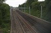
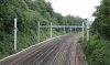
In looking at your image linked above, I can see that's a two track section of line, on the GWML, the route will look very similar to that, with the UK Series 1 equipment in place of the Chinese OLE equipment instead. The larger masts and either portals or booms are used for four track locations and also on two track locations where signal sighting or other issues make a twin track cantilever or portal structure the most appropriate solution.

If you have a look around, there's a mix of UK Series 1 and older OLE systems at Old Dalby - lots of photos on line, and there's a lot of photos of High Marnham showing the installation of the trail UK Series 1 kit up there too, which will give a good feel for the finished product and what the alternatives are.
 

pro4600

Member
Joined
6 Nov 2011
Messages
54
May be of interest that I drove from J26 to J31 on the M1 today. There are new gantries going in for managed motorway signage. On the more sensitive bit close to Hardwick Hall these are coloured brown rather than the usual galvanized finish. They seemed to stand out a bit less than the grey ones against a background that is predominantly trees, but with the trees as they are now green gantries would be less conspicuous. However perhaps this wouldn't be the case in winter when the motorway is probably much more visible due to said trees shedding their leaves. Not sure how well anything could disguise them when they are carrying red, orange and white illuminated signs though!

I think they all might be painted grey. Over the past few months many more where brown before they ended up grey. It might be they haven't got round to painting those ones yet.
 

QueensCurve

Established Member
Joined
22 Dec 2014
Messages
1,914
s. The Furrer und Frey Series 1 overhead being used on the GWML comes in a variety of configurations, and there are plenty of the two-track cantilever version already installed in places such as Pangbourne.

http://www.furrerfrey.ch/en/systems/Series-1.html#prettyPhoto.

That is so ugly by comparison with BR designs or the type used on the French-designed high speed lines.
--- old post above --- --- new post below ---
The ECML wiring isn't compatible with 140mph operation when two or more pantographs are used. 140mph operation with two or more pantographs is going to require the contact wire tension to be increased from around 12kN to 16.5kN, and that in turn needs a heavier duty contact wire with a cross section (it's formed with a groove so isn't actually circular) of 120mm2, an increase on the 107mm2 wire used at present, which increases the weight of the contact wire alone from around 920kg per km to 1035kg per km.

The catenary wire increases in size and weight too, you add additional droppers (the joins between the catenary wire and the contact wire) to support the weight, you increase the tension and the end result is a contact wire and catenary wire pair which is too heavy for the existing headspan design used on the ECML.

We have no design of headspan which works for 140mph with 2 or more pantographs and as I understand it, the tension and forces transmitted into a headspan from multiple pantographs at 140mph would almost certainly lower the mean time between failure rate to something lower than the ECML at present, unless you spend more money than you would installing portals, booms and twin track cantilevers, to design a headspan design with drastically increased wire diameters for the lateral wiring elements and specifying heavier duty insulators, lateral manual tensioners and possibly the masts themselves.

Are we in danger of setting the clock back here?

The 2 pantographs at high speed problem has been known since at least the 1970s. It was the reason why BR built the APT-P with 2 power cars in the middle of the set rather than one at each end - so they could share a pantograph.

Meanwhile, SNCF built the LGV Paris Sud-Est for 270km/h running (167mph) with only a single pantograph by putting a 25kV cable along the roof of the train to supply a power car at the other end. Atmittedly they used stiff OHLE with a high-pressure Faiveley Pantograph.

BR approached the high speed problem differently and developed the Brecknell Willis high speed pantograph which effectively became the British Standard. The design Brief for the new "pan" was - correct me if I am wrong - to work at high speeds (up to 250km/h) and was supposed to obviate, or at least reduce, the standing wave problem with multiple pantographs.

In the early 90s BR trialled 140mph running on the ECML using the new pantograph (albeit only one per train) and the Flashing Green "Fifth Aspect".

But now we will have IEP running on the ECML with 2 Faiveley pantographs per train - so we need to upgrade the ECML OHLE!

Could not DafT have specified the use of Brecknell Willis pantographs?

Since the TGV (and Pendolino???) have demonstrated the safety of the 25kV cable along the train, is it beyond the wit of man to connect 2 units? Even if it is not possible for a 25kV cable to connect 2 units could DafT not have specified longer units?
 
Status
Not open for further replies.

Top