-
Our new ticketing site is now live! Using either this or the original site (both powered by TrainSplit) helps support the running of the forum with every ticket purchase! Find out more and ask any questions/give us feedback in this thread!
You are using an out of date browser. It may not display this or other websites correctly.
You should upgrade or use an alternative browser.
You should upgrade or use an alternative browser.
Things we don't see at stations these days
- Thread starter Western 52
- Start date
- Status
- Not open for further replies.
Sponsor Post - registered members do not see these adverts; click here to register, or click here to log in
R
RailUK Forums
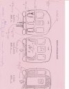
SUB's were still in service when I went through the South-Western Divisions Training School at Eastleigh, so I've attached the coupling diagram for EMU groups A (4SUB), D (2/4EPB) and E (4VEP, 4CIG). SUB's didn't have different ends, the connectors at each end were idential. However, after the mechanical and air couplings were made, the remaining three - Power, Control and Lighting HAD to be made in that order. I forget why but possibly because everything was derived from the traction current? REP's were slightly different owing to the ETH supply so had separate instructions, as were SE loco hauled trains (especially different sub classes of Cromptons cl33). Before you ask, yes, it was distributed on pink foolscap paper, which is why the image is cropped using an A4 scanner. The annotations are mineLT tube, trains, up to and including the 1938 stock, had A and B ends and there was a small plate by the drivers window to say if an A or B end. After that each axle had a letter, so trains and an A or D end. Later they had trains that were double ended but that complicated the couplers.
I think the standard Southern Region trains could couple any way - there was no 'end' designation on EPB,s CIG,s VEPS and Cl 33 for example
I dont know if earlier stock with different jumpers could couple either way. Did 4-SUB's need to be coupled the right way round?
On stations I used to love watching trains being coupled. The brake hoses (Vacuum and air), steam heat, ETH, control jumpers, the RCH lighting jumpers.
Attachments
75A
Established Member
Ah memories.SUB's were still in service when I went through the South-Western Divisions Training School at Eastleigh, so I've attached the coupling diagram for EMU groups A (4SUB), D (2/4EPB) and E (4VEP, 4CIG). SUB's didn't have different ends, the connectors at each end were idential. However, after the mechanical and air couplings were made, the remaining three - Power, Control and Lighting HAD to be made in that order. I forget why but possibly because everything was derived from the traction current? REP's were slightly different owing to the ETH supply so had separate instructions, as were SE loco hauled trains (especially different sub classes of Cromptons cl33). Before you ask, yes, it was distributed on pink foolscap paper, which is why the image is cropped using an A4 scanner. The annotations are mine
saddlestoneman
Member
Wheel tappers. I recall seeing one at Stoke station tapping the wheels on a south-bound London express with a long-handled hammer in the 1960s.
- Status
- Not open for further replies.