• Our booking engine at tickets.railforums.co.uk (powered by TrainSplit) helps support the running of the forum with every ticket purchase! Find out more and ask any questions/give us feedback in this thread!

Thinks - that catenary looks familiar

Status
Not open for further replies.

Dixie

Member
Joined
19 Feb 2012
Messages
152
Just watching a cab ride on YouTube, which finishes in the mountain town of Nesslau at the end of Suburban Line S2 from St Gallen. I was aware that recently the line had been refettled with new track and OHLE and some infrastructure work such as a few new bridges. As we were coming into Ebnat-Kappel I thought I'd recognise that OHLE anywhere!

1609018750713.png
 
Last edited:
Sponsor Post - registered members do not see these adverts; click here to register, or click here to log in
R

RailUK Forums

Domh245

Established Member
Joined
6 Apr 2013
Messages
8,426
Location
nowhere
Remember that the company who designed the OLE components used in GWEP (Furer & Frey) are swiss, so it shouldn't be surprising to see familiar designs over there
 

Dixie

Member
Joined
19 Feb 2012
Messages
152
Remember that the company who designed the OLE components used in GWEP (Furer & Frey) are swiss, so it shouldn't be surprising to see familiar designs over there

Indeed they are, and I should not have been the least surprised to see it. Only the Swiss could have such a pretty suburban line in what is really beautiful countryside, up in the mountains, miles from anywhere, but fortunately a few big villages and little towns strung along it which keeps it open.
 

Philip Phlopp

Established Member
Joined
31 May 2015
Messages
3,004
There is actual Series 1 OLE in use in both India and Taiwan.

Taiwan previously imported some of the old BR Mark 1 and I think Mark 3 OLE, possibly in combination with some of the stock they imported from the UK, though I'm sure foreign correspondents can confirm.
 

59CosG95

Established Member
Joined
18 Aug 2013
Messages
6,502
Location
Between Peterborough & Bedlington
British OLE in use abroad definitely merits a more detailed discussion on another thread, but I can say that Mk3 (or very similar) was exported to Hong Kong (MTR), Australia (Queensland Rail), and New Zealand (in the Auckland area). Both MTR and QR also have headspans...

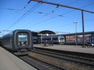
And Denmark of all places does have spanwire portals at some of its earlier electrified stations (such as Roskilde), which look very like Mk3 to me. The only difference is the steady arm, which looks to be a Siemens one.
1609101614387.png
 

nlogax

Established Member
Joined
29 May 2011
Messages
5,379
Location
Mostly Glasgow-ish. Mostly.
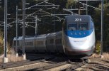
Was thinking the other day about this and Balfour Beatty’s electrification of the northern part of Amtrak’s Northeast Corridor in the late 90s. To my eye a lot of the OHLE looks like Mk3 or derived from it..is that anywhere near accurate?

For reference, this example from Rhode Island.

2E7871C3-4026-4BCE-AB56-8EB8E754318E.jpeg
 
Last edited:

edwin_m

Veteran Member
Joined
21 Apr 2013
Messages
24,967
Location
Nottingham
Was thinking the other day about this and Balfour Beatty’s electrification of the northern part of Amtrak’s Northeast Corridor in the late 90s. To my eye a lot of the OHLE looks like Mk3 or derived from it..is that anywhere near accurate?

For reference, this example from Rhode Island.

View attachment 87809
I believe BB did some work in the States derived from British designs, but I thought it was mk1 portals.
 

delticdave

Member
Joined
14 Apr 2017
Messages
449
The old Pennsy electrification to South Amboy (Nowadays the NJTransit North Jersey Coat Line was extended to Long Branch in the'80's & the OHLE looks very British, albeit somewhat taller. If you want some pix, try looking at Google Maps Satellite for Long Branch station, & use Streetview to peek at the level-crossing at "158 Western Ave Long Branch New Jersey". That's the end of the electrification, quite some way south from Long Branch Station & yards. NJT operate loco hauled trains from Long Branch to Bay Head, connecting with electric trains at Long Branch + some through trains to New York powered by ALP-45DP bi-mode locos.

I've ridden this line, probably 20+ years ago but I don't have any records other than undated prints. (Before Digital Cameras....)

HTH, DC
 

LNW-GW Joint

Veteran Member
Joined
22 Feb 2011
Messages
19,737
Location
Mold, Clwyd
Just watching a cab ride on YouTube, which finishes in the mountain town of Nesslau at the end of Suburban Line S2 from St Gallen. I was aware that recently the line had been refettled with new track and OHLE and some infrastructure work such as a few new bridges. As we were coming into Ebnat-Kappel I thought I'd recognise that OHLE anywhere!

Interesting that that Swiss route is not remotely high speed, while our Series 1 is targeted at (potential) 140mph lines.
The base structure looks to be concrete rather than GW's troublesome metal piles.
 

Philip Phlopp

Established Member
Joined
31 May 2015
Messages
3,004
Mark 2 coaches, almost forgot those.

Have you got any pictures of the Taiwan Series 1 installations? ISTR the Indian ones appeared on the Delhi Metro.

I do but none which can be shared due to copyright.
Interesting that that Swiss route is not remotely high speed, while our Series 1 is targeted at (potential) 140mph lines.
The base structure looks to be concrete rather than GW's troublesome metal piles.

Series 1 isn't a high speed OLE system, it's a high tension mixed traffic OLE system. It's robustness stems from the tension requirements (and in turn the wire diameter and then in turn the mass) needed for twin pantograph operation at upto 140mph and more specifically, the issue of three pantograph operation at 110mph which results in some serious issues in keeping the contact wire movement to a minimum and allowing the trailing pantograph to retain optimal contact with the contact wire.
 

36270k

Member
Joined
7 Jan 2015
Messages
210
Location
Trimley
The OHLE used on MTA Metro North lines looks to me to be very similar to UK mk1:

https://upload.wikimedia.org/wikipedia/commons/f/fe/MNRR_6100_(9550709846).jpg
The structure looks like an original New Haven RR one with new catenary.
May have been updated when the frequency was changed from 25hz to 60hz

The old Pennsy electrification to South Amboy (Nowadays the NJTransit North Jersey Coat Line was extended to Long Branch in the'80's & the OHLE looks very British, albeit somewhat taller. If you want some pix, try looking at Google Maps Satellite for Long Branch station, & use Streetview to peek at the level-crossing at "158 Western Ave Long Branch New Jersey". That's the end of the electrification, quite some way south from Long Branch Station & yards. NJT operate loco hauled trains from Long Branch to Bay Head, connecting with electric trains at Long Branch + some through trains to New York powered by ALP-45DP bi-mode locos.

I've ridden this line, probably 20+ years ago but I don't have any records other than undated prints. (Before Digital Cameras....)

HTH, DC
The Pennsy electrification to South Amboy dated from the 1930's
The original masts were 80 foot high and carried 132kv 25hz single phase substation feeders at the top.
This was long before a national grid existed.
Th first Pennsy electrification at 11000V 25hz was in Philadelphia in 1915
 
Last edited:

delticdave

Member
Joined
14 Apr 2017
Messages
449
Amtrak & NJT still use that Pennsy OHLE, the tall masts & high voltage feeders were in place when i was last there. (2006).
After Penn Station/Sunnyside yards Amtrak & some Metro North trains use the old New Haven masts but it's been tweaked, the catenary is quite modern + it's 12.5 kV 60hz in (Connecticut, because it's now state owned?). Beyond New Haven it's 25kV 60hz, with UK style OHLE.
 

Beebman

Member
Joined
17 Feb 2011
Messages
644
When I visited NYC in 2007 the OHLE on the section of line between Sunnyside Yards and New Rochelle over the Hell Gate Bridge looked very ancient with a complicated system of catenary wire support. When I returned in 2014 it had mostly been replaced by more modern equipment. As for the Pennsy electrification it seems to be similar to that used in the early 20th century by the Midi company in France in that the contact wire on curves is itself curved rather than a series of straight sections. The first picture linked below from France shows this very clearly. The second one is the best I can find of an example from PRR tracks:

https://mathcurve.com/surfaces.gb/reglee/catenairemidi.jpg
https://www.american-rails.com/images/197meirygvblo84t95747291203.jpg
 

AM9

Veteran Member
Joined
13 May 2014
Messages
14,282
Location
St Albans
When I visited NYC in 2007 the OHLE on the section of line between Sunnyside Yards and New Rochelle over the Hell Gate Bridge looked very ancient with a complicated system of catenary wire support. When I returned in 2014 it had mostly been replaced by more modern equipment. As for the Pennsy electrification it seems to be similar to that used in the early 20th century by the Midi company in France in that the contact wire on curves is itself curved rather than a series of straight sections. The first picture linked below from France shows this very clearly. The second one is the best I can find of an example from PRR tracks:

https://mathcurve.com/surfaces.gb/reglee/catenairemidi.jpg
https://www.american-rails.com/images/197meirygvblo84t95747291203.jpg
The first picture shows OLE strung over quite tight curves on what appears to be low speed sidings. Stagger isn't an issue for pantograph contact strip wear as it is so short and a small part of the total contact wires length. The catenary is angled to provide the pull throughout the curve. UK OLE mostly uses the catenary to provide vertical support/controlled sag, and uses registration arms to pull out on much shallower curves.
The second picture shows the centre and far side track wired with a compound catenary which historically was used in the UK, (last seen on the GEML around Stratford), but I can't see what the benefit of offsetting the catenary gives in terms of pantograph wear, especially as unless the tension is much higher, pantograph uplift could be cause the point of contact to move laterally.
No doubt the experts here could explain the dynamics of such a geometry.
 

59CosG95

Established Member
Joined
18 Aug 2013
Messages
6,502
Location
Between Peterborough & Bedlington
The first picture shows OLE strung over quite tight curves on what appears to be low speed sidings. Stagger isn't an issue for pantograph contact strip wear as it is so short and a small part of the total contact wires length. The catenary is angled to provide the pull throughout the curve. UK OLE mostly uses the catenary to provide vertical support/controlled sag, and uses registration arms to pull out on much shallower curves.
The second picture shows the centre and far side track wired with a compound catenary which historically was used in the UK, (last seen on the GEML around Stratford), but I can't see what the benefit of offsetting the catenary gives in terms of pantograph wear, especially as unless the tension is much higher, pantograph uplift could be cause the point of contact to move laterally.
No doubt the experts here could explain the dynamics of such a geometry.
The SICAT SX system (being installed in Denmark & a bit of Hungary IIRC) uses a similar offset of the catenary & contact. (See attached)
IIRC the staggered catenary gives a better stiffness to the OLE.Screenshot_20201229-132011_Drive.jpgScreenshot_20201229-131940_Drive.jpg
 

Philip Phlopp

Established Member
Joined
31 May 2015
Messages
3,004
The first picture shows OLE strung over quite tight curves on what appears to be low speed sidings. Stagger isn't an issue for pantograph contact strip wear as it is so short and a small part of the total contact wires length. The catenary is angled to provide the pull throughout the curve. UK OLE mostly uses the catenary to provide vertical support/controlled sag, and uses registration arms to pull out on much shallower curves.
The second picture shows the centre and far side track wired with a compound catenary which historically was used in the UK, (last seen on the GEML around Stratford), but I can't see what the benefit of offsetting the catenary gives in terms of pantograph wear, especially as unless the tension is much higher, pantograph uplift could be cause the point of contact to move laterally.
No doubt the experts here could explain the dynamics of such a geometry.

You've largely covered it - lack of registration arms to provide the desired contact wire geometry means you need to use the entire catenary system to shape the contact wire to suit the curvature of the track. Which you can indeed do by tensioning of the system, compounding of the catenary system, choice selection of dropper length and so on.

The preferred system here in Britain is straight wire runs with staggering through the use of registration arms. This means the wire is run in a succession of straight sections (even on curves) with the deployment of push off or pull off cantilevers as required. We use, on many curves, a continual succession of one type of cantilever arm (say all push off or all pull off) which when correctly positioned will allow the contact wire geometry to be maintained whilst providing stagger. The train/pantograph movement on the curve means even with the masts undertaking continuous push off or pull off, the pantograph carbon will move in relation to the contact wire, evening out wear.

Staggering gives a better stiffness by virtue of being able to dampen travelling waves through the use of the registration arm. It does also make tensioning rather easier since the shape of the catenary isn't strongly dictated by the overall tension of the system.
 

AM9

Veteran Member
Joined
13 May 2014
Messages
14,282
Location
St Albans
You've largely covered it - lack of registration arms to provide the desired contact wire geometry means you need to use the entire catenary system to shape the contact wire to suit the curvature of the track. Which you can indeed do by tensioning of the system, compounding of the catenary system, choice selection of dropper length and so on.

The preferred system here in Britain is straight wire runs with staggering through the use of registration arms. This means the wire is run in a succession of straight sections (even on curves) with the deployment of push off or pull off cantilevers as required. We use, on many curves, a continual succession of one type of cantilever arm (say all push off or all pull off) which when correctly positioned will allow the contact wire geometry to be maintained whilst providing stagger. The train/pantograph movement on the curve means even with the masts undertaking continuous push off or pull off, the pantograph carbon will move in relation to the contact wire, evening out wear.

Staggering gives a better stiffness by virtue of being able to dampen travelling waves through the use of the registration arm. It does also make tensioning rather easier since the shape of the catenary isn't strongly dictated by the overall tension of the system.
Thanks for that info. The proposition of getting better stiffness with the stagger from unidirectional tension on curves is particularly interesting, especially as the moments at the points of registration are in both X and Y planes. In the pictured offset catenary examples, that energy is dissipated in the whole conductor/dropper/catenary structure which with a much higher mass, I assume, would have a lower resonance (f0) and higher Q, making multi-pantograph operation even more problematic. That's before the liveliness of the headspans comes into play. The use of compound catenary just compounds* the mass and adds to the woes of the OLE.
Was the higher mass issue part of the move away from compound catenary in the UK? I assume that the other shortcoming was the uncompensated fixed tension used with it.
* apologies for the pun :)

p.s. I like the term "evening out wear" ;)
 

Philip Phlopp

Established Member
Joined
31 May 2015
Messages
3,004
Thanks for that info. The proposition of getting better stiffness with the stagger from unidirectional tension on curves is particularly interesting, especially as the moments at the points of registration are in both X and Y planes. In the pictured offset catenary examples, that energy is dissipated in the whole conductor/dropper/catenary structure which with a much higher mass, I assume, would have a lower resonance (f0) and higher Q, making multi-pantograph operation even more problematic. The use of compound catenary just compounds* the mass and adds to the woes of the OLE.
Was the higher mass issue part of the move away from compound catenary in the UK? I assume that the other shortcoming was the uncompensated fixed tension used with it.
* apologies for the pun :)

Fixed tension was the main issue - given the significant range of temperatures experienced in the UK (in respect of expansion and contraction of contact wire system) there really needs to be some form of auto-tensioning. Don't make me do frequency, resonance and wave propogation calculations at Christmas, what I will say is that tensioning and the impact of wave interactions (both in and out of phase) will dictate for the most part how that system will behave with multiple pantographs. If there's amplification (which may be because of a lack of damping from the registration arms present in the system) then clearly multiple pantograph operation will be more problematic, if there's suppression that may be helpful to multiple pantograph operation with the proviso that such suppression can often come at a cost of wear/damage to insulators and other components.

The weight (or rather, the amount of material needed) has been a secondary driver through all of the OLE development, Mark 2 reduced the copper content of the system, Mark 3 reduced the amount of steelwork further and the move away from Series 1 to Series 2 (or MS125, as it now is within the UK Master Series nomenclature) is again (partially) being driven by system mass derived cost.
 

AM9

Veteran Member
Joined
13 May 2014
Messages
14,282
Location
St Albans
The SICAT SX system (being installed in Denmark & a bit of Hungary IIRC) uses a similar offset of the catenary & contact. (See attached)
IIRC the staggered catenary gives a better stiffness to the OLE.View attachment 87868View attachment 87869
I can see that the system shown in the in the leaflet might be 'stiffer' than a conventional perpendicular geometry, but in essence it isn't that much different to the style used in the UK. The two pictures attached to post #18 however show that in each case, the whole OLE is only anchored via the catenary insulators, meaning that the full weight of the catenary/droppers/conductor is free to oscillate, (thereby giving a lower resonant frequency than if it was damped by semi-compliant conductor registration hardware).
Fixed tension was the main issue - given the significant range of temperatures experienced in the UK (in respect of expansion and contraction of contact wire system) there really needs to be some form of auto-tensioning. Don't make me do frequency, resonance and wave propogation calculations at Christmas, what I will say is that tensioning and the impact of wave interactions (both in and out of phase) will dictate for the most part how that system will behave with multiple pantographs. If there's amplification (which may be because of a lack of damping from the registration arms present in the system) then clearly multiple pantograph operation will be more problematic, if there's suppression that may be helpful to multiple pantograph operation with the proviso that such suppression can often come at a cost of wear/damage to insulators and other components.

The weight (or rather, the amount of material needed) has been a secondary driver through all of the OLE development, Mark 2 reduced the copper content of the system, Mark 3 reduced the amount of steelwork further and the move away from Series 1 to Series 2 (or MS125, as it now is within the UK Master Series nomenclature) is again (partially) being driven by system mass derived cost.

Sorry to wake the work brain from its seasonal break. :) The electrical analogy was coming to me.
Thanks for the explanations.
 

SouthEastBuses

On Moderation
Joined
15 Nov 2019
Messages
1,800
Location
uk
British OLE in use abroad definitely merits a more detailed discussion on another thread, but I can say that Mk3 (or very similar) was exported to Hong Kong (MTR), Australia (Queensland Rail), and New Zealand (in the Auckland area). Both MTR and QR also have headspans...

And Denmark of all places does have spanwire portals at some of its earlier electrified stations (such as Roskilde), which look very like Mk3 to me. The only difference is the steady arm, which looks to be a Siemens one.
View attachment 87804

I believe Transperth in Western Australia (Perth) also uses British style electrification, so you've got two railway systems in Australia using British OLE.
 

WAO

Member
Joined
10 Mar 2019
Messages
666
IIRC (I often don't), Mk3b was exported to the KCR (Kowloon Canton Railway) for its 1982 electrification, "in Typhoon-proof mode" (source: Modern Railways).

So it can be done, but with headspans?

WAO
 

AM9

Veteran Member
Joined
13 May 2014
Messages
14,282
Location
St Albans
IIRC (I often don't), Mk3b was exported to the KCR (Kowloon Canton Railway) for its 1982 electrification, "in Typhoon-proof mode" (source: Modern Railways).

So it can be done, but with headspans?

WAO
Yes, I think that was part of the package that included the GEC built trains .
Edit: Looking at some of the KCR pictures, it seems that the '80s electrification consisted of full gantries with lateral strings stabilising the floating registration arms and some single cantilevers on open stretches. So a bit more robust than the cat's cradles on the ECML.
Ironically, there's also a picture of an electric loco in the '60s where the OLE above is a full head span! So maybe the design of the '80s kit was based on (bitter) experience.
 
Last edited:

SouthEastBuses

On Moderation
Joined
15 Nov 2019
Messages
1,800
Location
uk
Was thinking the other day about this and Balfour Beatty’s electrification of the northern part of Amtrak’s Northeast Corridor in the late 90s. To my eye a lot of the OHLE looks like Mk3 or derived from it..is that anywhere near accurate?

For reference, this example from Rhode Island.

View attachment 87809

To me, they resemble more the type of electrification used on the LGV high speed lines in France and HS1 rather than an Mk3.
 
Status
Not open for further replies.

Top