• Our booking engine at tickets.railforums.co.uk (powered by TrainSplit) helps support the running of the forum with every ticket purchase! Find out more and ask any questions/give us feedback in this thread!

Signal Passed at Danger (SPAD) and near miss at Sileby Junction 05/05/2021

Status
Not open for further replies.

GC class B1

Member
Joined
19 Jun 2021
Messages
447
Location
East midlands
Could one of the signalling specialists on the forum answer a question. In the earlier SPAD with the two class 57s and an unbraked class 710 EMU, the report stated that the distance between the previous signal and the SPAD signal was 1320 metres and the line speed approaching the previous signal was 65 MPH. For the Sileby SPAD the report stated that distance from the previous signal to the SPAD signal was 2580 metres. In the clause 51 of the report into the SPAD at Loughborough, RAIB report No 10/2020, the driver stated that the signalling distances on both the fast (maximum speed110 MPH) and slow lines were the same and that as a result the braking distance on the slow lines were more than necessary. It seems that this lead the driver to incorrectly believe that he could therefore brake at a lower rate in order to stop before the red signal. I wonder why at the apparently similar similar locations the slow line signal spacings in the Sileby area were almost double those in the Loughborough area. The driver of the train involved in the Loughborough SPAD appears to have been mislead by the variations in signal spacing in this area.
 
Last edited:
Sponsor Post - registered members do not see these adverts; click here to register, or click here to log in
R

RailUK Forums

Tomnick

Established Member
Joined
10 Jun 2005
Messages
5,840
Could one of the signalling specialists on the forum answer a question. In the earlier SPAD with the two class 57s and an unbraked class 710 EMU, the report stated that the distance between the previous signal and the SPAD signal was 1320 metres and the line speed approaching the previous signal was 65 MPH. For the Sileby SPAD the report stated that distance from the previous signal to the SPAD signal was 2580 metres. In the clause 51 of the report into the SPAD at Loughborough, RAIB report No 10/2020, the driver stated that the signalling distances on both the fast (maximum speed110 MPH) and slow lines were the same and that as a result the braking distance on the slow lines were more than necessary. It seems that this lead the driver to incorrectly believe that he could therefore brake at a lower rate in order to stop before the red signal. I wonder why at the apparently similar similar locations the slow line signal spacings in the Sileby area were almost double those in the Loughborough area. The driver of the train involved in the Loughborough SPAD appears to have been mislead by the variations in signal spacing in this area.
The Down Fast signalling transitions from 3-aspect to 4-aspect between Barrow and Loughborough. The signal section in question is the first section that's shorter as a result.
 

Hairy Bear

Member
Joined
13 Feb 2011
Messages
345
Location
Derbyshire
Having driven this section for over 30 years I can tell you that the signal spacing had no bearing on the two incidents and the spad's were down to the actions of both drivers.
The Loughborough South one which had 2 top n tail 57's and an unbraked unit, was a combination of excess speed and the ability of two 57's to brake the load with the driver not braking early enough and with sufficient reduction in brake pipe pressure in time to stop.
The Sileby incident was down to the machine driver not reacting to the single yellow and braking too late to safely stop in time, almost certainly down to his fatigue.
The signal spacing on the section between Wellingborough and Loughborough is a very mixed bag and requires very careful route learning to know exactly were your next signal is and how far you got to stop. Neither driver seemed to have grasped that.
 
Joined
29 Oct 2021
Messages
180
Location
Newton Abbot
Having driven this section for over 30 years I can tell you that the signal spacing had no bearing on the two incidents and the spad's were down to the actions of both drivers.
The Loughborough South one which had 2 top n tail 57's and an unbraked unit, was a combination of excess speed and the ability of two 57's to brake the load with the driver not braking early enough and with sufficient reduction in brake pipe pressure in time to stop.
The Sileby incident was down to the machine driver not reacting to the single yellow and braking too late to safely stop in time, almost certainly down to his fatigue.
The signal spacing on the section between Wellingborough and Loughborough is a very mixed bag and requires very careful route learning to know exactly were your next signal is and how far you got to stop. Neither driver seemed to have grasped that.
Yes of course you are fundamentally correct.

With the times two 57 and 710 consist, regardless of anything TOPS or tables, basic physics stands out. Lots of mass and relatively low retarding force not forgetting 15 seconds freewheel.

Regarding the grinder consist, excess braking distance ( contrary to best practise) did not help. I guess if the driver had not been fatigued, he would have applied non-technical skills and done something at the cautionary signal.

These incidents do highlight the demands placed on drivers, and the consequences, not just basic safety, but also drivers livelihood and reputation.
 

Nicholas Lewis

Established Member
Joined
9 Aug 2019
Messages
6,129
Location
Surrey
Whilst fatigue is cited as an underlying factor it seems to me the only way to deal with the variability of driver behaviour, from whatever cause, is to have vehicles on the network that must be able to deliver the 7.5%g braking rate that TPWS is designed to. If they can't then there maximum speed needs reducing no need to overcomplicate this and issue more recommendations for industry participants to prevaricate over for years.
 

GC class B1

Member
Joined
19 Jun 2021
Messages
447
Location
East midlands
Whilst fatigue is cited as an underlying factor it seems to me the only way to deal with the variability of driver behaviour, from whatever cause, is to have vehicles on the network that must be able to deliver the 7.5%g braking rate that TPWS is designed to. If they can't then there maximum speed needs reducing no need to overcomplicate this and issue more recommendations for industry participants to prevaricate over for years.
I think this is over simplistic. Railway operation, except those on dedicated high speed lines must take into account the necessarily different braking performance of different trains. In order to meet the needs of the country, passenger and freight trains will have very different braking rates. Infrastructure has been designed to meet these significantly different require and rolling stock must meet the braking rates that the infrastructure has been designed to accomoadte. Railway Group standards and the newer Railway Industry standards along with TSIs (Technical Standards for Interoperability) are intended to ensure compatibility between the infrastructure and the vehicles that operate on it. In some instances it is necessary for trains to operate that do not meet all the requirements of the infrastructure and where this is because the braking performance is not sufficient to operate at the maximum line speed for the location, the train speed is reduced.
As far as TPWS functionality is concerned, my earlier posts have shown that this is possible with trains with different braking rates on the same infrastructure.

I am not in any way a signalling specialist but i have read this report with a great deal of interest, in particular the signal distances and have researched what I believe to be the applicable standards. There are some points that have occurred to me that I think may be of interest to forum members and those with specialist knowledge may be able to comment to assist my understanding.
I believe that the maximum speed on the fast line in the Syston to Sileby area is 110 MPH. Signal LR 473 is about 4 miles from Leicester station. I understand all passengers trains on the down fast line will have stopped at Leicester it therefore it is unlikely they will generally have reached this speed by the time they reach the down fast line signal at the same location as LR 473 and will be highly unlikely to exceed that speed. As the HST trains previously in service on this line and the present Class 180 and 222 trains are braked at least at 9% g, then Appendix C to GK/RT0075 is applicable to the down fast line. From this document the minimum the signal braking distance for the down fast line on a 1 in 400 falling gradient is 1653 metres. Paragraph G 2.7.3.9 of RIS-0703-CCS recommends a signal spacing between 110% and 150% of the minimum signalling braking distance. With the same signal spacing on the down fast and slow lines, working to the recommended signal distances would give a down slow signal spacing between 1818 and 2480 metres between signals LR 473 and LR 477. As this section is 2580 metres it exceeds the maximum recommended distance on the down fast by 100 metres. From these calculations I can understand why the incident driver may have believed that he would stop his train well before the red signal with only a light brake application. I am not suggesting that the down fast line signal spacings should be changed however with this apparently longer than normal signal spacing for the maximum line speed, if the line speed on the down slow is not more than 65MPH, there may be an opportunity to position another signal on the down slow line half way between LR 473 and LR 477. I note that in previous posts there has been a discussion about double blocking ( I.e. a red signal at the signal before the signal protecting the point of conflict). The provision of another signal on the down slow line would permit this without compromising line capacity.
The driver of the train involved in the SPAD at Loughborough, RAIB report No 10/2020 was of the incorrect belief that the signal distances on the slow line were far more than necessary for the lower line speed because they were located at the same distance as the fast lines. Whilst the reason for the SPAD was that the formation had insufficient braking capability for the weight of the consist, it seems possible that the unusually long section after joining the main line at Syston to signal LR 477 gave this impression. As this seems to be the only signal section between Leicester and Loughborough that is this length, adding an intermediate signal would assist b drivers by achieving a more uniform signal spacing.
Good practice in risk mitigation is to both ensure consistency wherever possible and to use the available technology to design out any avoidable risks. My thought is that providing an intermediate slow line signal between LR 473 and LR 477 would reduce the risk of SPADs occurring and most importantly encroaching the conflict point. There seem to have statistically been more than the average number of incidents in this area, which may in part be the result of a greater number of non conventional train movements.
 
Last edited:

Nicholas Lewis

Established Member
Joined
9 Aug 2019
Messages
6,129
Location
Surrey
I think this is over simplistic. Railway operation, except those on dedicated high speed lines must take into account the necessarily different braking performance of different trains. In order to meet the needs of the country, passenger and freight trains will have very different braking rates. Infrastructure has been designed to meet these significantly different require and rolling stock must meet the braking rates that the infrastructure has been designed to accomoadte. Railway Group standards and the newer Railway Industry standards along with TSIs (Technical Standards for Interoperability) are intended to ensure compatibility between the infrastructure and the vehicles that operate on it. In some instances it is necessary for trains to operate that do not meet all the requirements of the infrastructure and where this is because the braking performance is not sufficient to operate at the maximum line speed for the location, the train speed is reduced.
As far as TPWS functionality is concerned, my earlier posts have shown that this is possible with trains with different braking rates on the same infrastructure.

I am not in any way a signalling specialist but i have read this report with a great deal of interest, in particular the signal distances and have researched what I believe to be the applicable standards. There are some points that have occurred to me that I think may be of interest to forum members and those with specialist knowledge may be able to comment to assist my understanding.
I believe that the maximum speed on the fast line in the Syston to Sileby area is 110 MPH. Signal LR 473 is about 4 miles from Leicester station. I understand all passengers trains on the down fast line will have stopped at Leicester it therefore it is unlikely they will generally have reached this speed by the time they reach the down fast line signal at the same location as LR 473 and will be highly unlikely to exceed that speed. As the HST trains previously in service on this line and the present Class 180 and 222 trains are braked at least at 9% g, then Appendix C to GK/RT0075 is applicable to the down fast line. From this document the minimum the signal braking distance for the down fast line on a 1 in 400 falling gradient is 1653 metres. Paragraph G 2.7.3.9 of RIS-0703-CCS recommends a signal spacing between 110% and 150% of the minimum signalling braking distance. With the same signal spacing on the down fast and slow lines, working to the recommended signal distances would give a down slow signal spacing between 1818 and 2480 metres between signals LR 473 and LR 477. As this section is 2580 metres it exceeds the maximum recommended distance on the down fast by 100 metres. From these calculations I can understand why the incident driver may have believed that he would stop his train well before the red signal with only a light brake application. I am not suggesting that the down fast line signal spacings should be changed however with this apparently longer than normal signal spacing for the maximum line speed, if the line speed on the down slow is not more than 65MPH, there may be an opportunity to position another signal on the down slow line half way between LR 473 and LR 477. I note that in previous posts there has been a discussion about double blocking ( I.e. a red signal at the signal before the signal protecting the point of conflict). The provision of another signal on the down slow line would permit this without compromising line capacity.
The driver of the train involved in the SPAD at Loughborough, RAIB report No 10/2020 was of the incorrect belief that the signal distances on the slow line were far more than necessary for the lower line speed because they were located at the same distance as the fast lines. Whilst the reason for the SPAD was that the formation had insufficient braking capability for the weight of the consist, it seems possible that the unusually long section after joining the main line at Syston to signal LR 477 gave this impression. As this seems to be the only signal section between Leicester and Loughborough that is this length, adding an intermediate signal would assist b drivers by achieving a more uniform signal spacing.
Good practice in risk mitigation is to both ensure consistency wherever possible and to use the available technology to design out any avoidable risks. My thought is that providing an intermediate slow line signal between LR 473 and LR 477 would reduce the risk of SPADs occurring and most importantly encroaching the conflict point. There seem to have statistically been more than the average number of incidents in this area, which may in part be the result of a greater number of non conventional train movements.
I read in the report that the area was controlled from EMCC and presumed it was recently resignalled but that is further north when Trent PSB was replaced. So im surmising that on the ground its the original trackside signalling which was installed mid 80's which would have been to be lower standards than would apply now and certainly overbraked signals were quite prevalent on schemes in the 80's.

I still standby my view that any vehicle that can't achieve 7.5%g braking rate that TPWS is designed to needs to have the risk managed by reduced speed or other measures.
 

GC class B1

Member
Joined
19 Jun 2021
Messages
447
Location
East midlands
I read in the report that the area was controlled from EMCC and presumed it was recently resignalled but that is further north when Trent PSB was replaced. So im surmising that on the ground its the original trackside signalling which was installed mid 80's which would have been to be lower standards than would apply now and certainly overbraked signals were quite prevalent on schemes in the 80's.

I still standby my view that any vehicle that can't achieve 7.5%g braking rate that TPWS is designed to needs to have the risk managed by reduced speed or other measures.
I am also pretty sure that the signalling infrastructure in this area has not been changed much since the 1980s. I read the incident report to mean that Leicester Power signal box had closed and control was transferred to the EMCC.
The train in the incident didn’t brake at 7.5%g and was restricted to 55 MPH as you suggest, but still passed the red signal and the conflict point. My posts relate to dealing with the risk of SPADs, and particularly the risk of subsequently passing conflict points. The incident train complied with the applicable braking table in GM/RT2045 issue 4, and I suggested in my post number 67 how the SPAD risk at signal LR 477, for trains that are braked to table A of GM/RT2045 could be managed.

A further point regarding compatibility with vehicle brake performance and TPWS design is that as stated in this report, OSS loops are designed for a passenger vehicle Emergency brake application deceleration rate of 12% g. The deceleration rate for Sprinters, and class 158, and I believe the more modern DMUs such as class 170 and 196 is 9%g and not the TPWS design figure of 12%g.
 
Last edited:

Signal Head

Member
Joined
26 May 2013
Messages
398
A further point regarding compatibility with vehicle brake performance and TPWS design is that as stated in this report, OSS loops are designed for a passenger vehicle Emergency brake application deceleration rate of 12% g. The deceleration rate for Sprinters, and class 158, and I believe the more modern DMUs such as class 170 and 196 is 9%g and not the TPWS design figure of 12%g.
Which is probably why, for several years now, on renewals and alterations, it is generally the practice to review TPWS fitments to see if they can be improved and achieve effectiveness at 9% (see my earlier post for examples).
 
Joined
29 Oct 2021
Messages
180
Location
Newton Abbot
Which is probably why, for several years now, on renewals and alterations, it is generally the practice to review TPWS fitments to see if they can be improved and achieve effectiveness at 9% (see my earlier post for examples).
The theory of TPWS is nothing more than suvat kinematic equations. I remember being taught this standard of mathematical physics at Secondary Modern in the 1970s as a CSE pupil. The issue is: set distance, set trip speed, against acceleration risk.
 

E27007

Member
Joined
25 May 2018
Messages
680
The theory of TPWS is nothing more than suvat kinematic equations. I remember being taught this standard of mathematical physics at Secondary Modern in the 1970s as a CSE pupil. The issue is: set distance, set trip speed, against acceleration risk.
Remember TPWS was not the preferred solution, after Ladbroke Grove 1999, the railway were under great pressure to take action immediately and in a short time frame. TPWS could be installed easily to traction and to the signalling system without major intervention or redesign of existing interlocking systemk. ATP was the preferred solution over TPWS, but required a lot more time and work to implement.

The suvat kinematics, ie Newton? F=ma etc? A bit more complex than that, maximum deceleration depends on railhead conditions, in leaf-fall contaminated railhead conditions, the wheel to rail coefficient of friction can be zero, therefore deceleration under braking is zero, and those OTMs are often the first units of the morning to move after the line has been under possession for 6 hours or more, the railhead nicely contaminated overnight, and OTMs have the least provision for wheelslide mitigation under braking, lacking driver controlled sanding gear, or automatic one-shot emergency sanding systems when TPWS activates the brakes.
 

edwin_m

Veteran Member
Joined
21 Apr 2013
Messages
24,929
Location
Nottingham
Remember TPWS was not the preferred solution, after Ladbroke Grove 1999, the railway were under great pressure to take action immediately and in a short time frame. TPWS could be installed easily to traction and to the signalling system without major intervention or redesign of existing interlocking systemk. ATP was the preferred solution over TPWS, but required a lot more time and work to implement.
The development of TPWS started around 1994 - I was there - with a realisation by BR and the embryo Railtrack that ATP wasn't a viable solution due to installation time and other difficulties not just cost. This led to a number of "SPAD Reduction and Mitigation" initiatives of which the most successful were what become TPWS and the driver's reminder appliance. The functionality was established first, that is establishing a maximum speed at the signal and again somewhere on the approach to stop before the point of confict. I think this was a simple SUVAT (v^2=u^2+2as being the most relevant equation) but it probably allowed for brake response time and other matters. Adhesion issues were being considered at the same time and this was probably one factor leading ultimately to the re-emergence of sanders. Analysis of accidents going back to 1968 predicted that TPWS would avoid about 70% of the casualties that would be avoided by ATP - something the Uff-Cullen report was quite skeptical of but has been generally borne out by statistics since then.

So yes it was chosen as a way forward instead of ATP, but at the time of Ladbroke Grove TPWS was ready to go and awaiting funding for deployment. The advent of ETCS has changed the equation somewhat compared to 1980s-vintage ATP, in that compatible equipment is available from multiple suppliers and there is little risk of component obsolescence.
 

snowball

Established Member
Joined
4 Mar 2013
Messages
7,745
Location
Leeds
The suvat kinematics, ie Newton? F=ma etc? A bit more complex than that,
I wasn't familiar with the term "suvat" that ocurred in the post so I looked it up. It turned out it's a term for a bunch of very familiar equations about motion with constant acceleration, linking s, u, v, a and t (the distance, initial and final velocities, acceleration and time). An obvious term once you know it.

Once you mention force it's no longer kinematics.
 

GC class B1

Member
Joined
19 Jun 2021
Messages
447
Location
East midlands
Remember TPWS was not the preferred solution, after Ladbroke Grove 1999, the railway were under great pressure to take action immediately and in a short time frame. TPWS could be installed easily to traction and to the signalling system without major intervention or redesign of existing interlocking systemk. ATP was the preferred solution over TPWS, but required a lot more time and work to implement.

The suvat kinematics, ie Newton? F=ma etc? A bit more complex than that, maximum deceleration depends on railhead conditions, in leaf-fall contaminated railhead conditions, the wheel to rail coefficient of friction can be zero, therefore deceleration under braking is zero, and those OTMs are often the first units of the morning to move after the line has been under possession for 6 hours or more, the railhead nicely contaminated overnight, and OTMs have the least provision for wheelslide mitigation under braking, lacking driver controlled sanding gear, or automatic one-shot emergency sanding systems when TPWS activates the brakes.
You are of course correct that it is necessary for the wheel/rail coefficient of friction to be sufficient for the retardation rate produced by the vehicle braking system. This however does not invalidate the calculation of braking distance, using the laws of motion (suvat), but means that in very low adhesion the deceleration rate will be less than the rate selected by the driver as a result of wheel slide and /or the action of wheel slide protection (WSP) where this is fitted. The stoping distance will still be calculated using the (lower) deceleration rate.
The vehicles in the rail grinder train involved in this incident are very heavy and have tread brakes so are much less vulnerable to very low adhesion. As a point I have never heard of zero wheel/rail coefficient of friction and I am pretty sure this is impossible.
 

E27007

Member
Joined
25 May 2018
Messages
680
You are of course correct that it is necessary for the wheel/rail coefficient of friction to be sufficient for the retardation rate produced by the vehicle braking system. This however does not invalidate the calculation of braking distance, using the laws of motion (suvat), but means that in very low adhesion the deceleration rate will be less than the rate selected by the driver as a result of wheel slide and /or the action of wheel slide protection (WSP) where this is fitted. The stoping distance will still be calculated using the (lower) deceleration rate.
The vehicles in the rail grinder train involved in this incident are very heavy and have tread brakes so are much less vulnerable to very low adhesion. As a point I have never heard of zero wheel/rail coefficient of friction and I am pretty sure this is impossible.
I am a retired OTM driver, very experienced and incident-free in leaf fall driving conditions, tread brakes make no difference, railhead adhesion can be so tiny, the wheels simply slow down and cease to rotate, and this happens without even applying the brakes, there can be inadequate adhesion to even reinstate wheel rotation ( the wheels simply glide upon the contaminated rails). how do we stop an OTM in extreme leaf fall conditions, Answer, route knowledge, using careful control of speed, way below linespeed, and use of gradients (gravity). We really earn our money under leaf fall driving, it is not for the faint hearted.
ps Signallers are very aware of the difficulties of leaf fall driving for an OTM , and the best Signallers will keep several blocks of signals ahead of an OTM clear when the OTM is running back to a depot/stablingand is needs to stop and reverse at a signal to avoid paperwork/grief of the OTM sliding past the red
 
Last edited:

GC class B1

Member
Joined
19 Jun 2021
Messages
447
Location
East midlands
I am a retired OTM driver, very experienced and incident-free in leaf fall driving conditions, tread brakes make no difference, railhead adhesion can be so tiny, the wheels simply slow down and cease to rotate, and this happens without even applying the brakes, there can be inadequate adhesion to even reinstate wheel rotation ( the wheels simply glide upon the contaminated rails). how do we stop an OTM in extreme leaf fall conditions, Answer, route knowledge, using careful control of speed, way below linespeed, and use of gradients (gravity). We really earn our money under leaf fall driving, it is not for the faint hearted.
ps Signallers are very aware of the difficulties of leaf fall driving for an OTM , and the best Signallers will keep several blocks of signals ahead of an OTM clear when the OTM is running back to a depot/stablingand is needs to stop and reverse at a signal to avoid paperwork/grief of the OTM sliding past the red
I found some parts of your post a bit puzzling. You state that wheelsets of the OTM you refer to have locked without a brake application. I can only assume that this is because of a very high rotational resistance. Has this occurred when the machine is in working mode whereby from my understanding both traction and braking are controlled by the hydrostatic system which will therefore always be filled with oil. If I am correct the powered wheelsets will have either traction or braking force applied all the time the machine is working.
 

E27007

Member
Joined
25 May 2018
Messages
680
I found some parts of your post a bit puzzling. You state that wheelsets of the OTM you refer to have locked without a brake application. I can only assume that this is because of a very high rotational resistance. Has this occurred when the machine is in working mode whereby from my understanding both traction and braking are controlled by the hydrostatic system which will therefore always be filled with oil. If I am correct the powered wheelsets will have either traction or braking force applied all the time the machine is working.
I did not state locked, I stated a wheelset slows down and ceases to rotate, not enouigh railhead friction to maintain roll.. Not in working mode in a possession, outside the possession during transit, ie running as a train, normal signalling, on open road as a class 6 (60 mph), or class 7 (40mph) or whatever in between as per OTM certification. Not all OTMs have hydrostatic transmissions, older OTMs, still plenty in service, have ZF transmissions, just like driving an automatic car, a gear selector on the cab desk, 3 forward and 3 reverse (sic) and a throttle for engine rpm / power, a ZF will coast for miles from speed with the throttle closed, there is minimal engine braking, and actually easier to handle than the hydrastatic systems, coasting distances are very predictable for the perfectionist driver.
The transmission you refer to, the diesel engine drives a powerful hydraulic pump into a hydraulic circuit, power is diverted from the circuit to hydraulic traction motors by a circuit we call a baffle plate, the driver's power handle controls the baffle plate. and the driving force of the hydraulic traction motors. It is not part of the braking system, though there is drag in the motors when coasting. The diesel engine runs at full rpm at all times when moving above walking pace, even when coasting or decelerating or braking, the diesel engine must run at full rpm or there will be a pressure backfeed with a high risk of blowing up the pump, in fact if the diesel engine fails and shuts down on the move, we must stop quickly. I withdraw the value of railhead coefficient of friction as zero, nothing has a zero coefficent of friction except possibly supercooled helium in the superfluid state, but I replace zero with a number of a decimal point followed by several zeroes, ie a very low number. Those hydraulic transmissions require frequent setting up by the fitters, they hate the job! They have to adjust valves to equalise drive performance of the hydraulic motors, ( 1 motor to an axle, a six axle OTM will have 2 or 3 powered axles. The motors soon go out of balance after a few days, one motor may become a "dragger", another may become too lively, again more grief for the OTM driver to master in bad railhead conditions
 

millemille

Member
Joined
28 Jul 2011
Messages
353
... lacking driver controlled sanding gear...
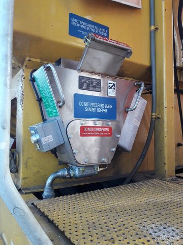
You may be interested to know that a couple of years ago my company designed, manufactured and installed a driver controlled sander on a fleet of NR OTM's...

ZikT1l.jpg


...designed to fit in the same space envelope as the OEM one-shot sanders it gives a 10 second burst of sand at 2kg/min when the driver presses the sander button on the desk (that used to fire the one shots) and contains enough sand for over 60 shots.

From all accounts the drivers like it...
 
Joined
29 Oct 2021
Messages
180
Location
Newton Abbot
I did not state locked, I stated a wheelset slows down and ceases to rotate, not enouigh railhead friction to maintain roll.. Not in working mode in a possession, outside the possession during transit, ie running as a train, normal signalling, on open road as a class 6 (60 mph), or class 7 (40mph) or whatever in between as per OTM certification. Not all OTMs have hydrostatic transmissions, older OTMs, still plenty in service, have ZF transmissions, just like driving an automatic car, a gear selector on the cab desk, 3 forward and 3 reverse (sic) and a throttle for engine rpm / power, a ZF will coast for miles from speed with the throttle closed, there is minimal engine braking, and actually easier to handle than the hydrastatic systems, coasting distances are very predictable for the perfectionist driver.
The transmission you refer to, the diesel engine drives a powerful hydraulic pump into a hydraulic circuit, power is diverted from the circuit to hydraulic traction motors by a circuit we call a baffle plate, the driver's power handle controls the baffle plate. and the driving force of the hydraulic traction motors. It is not part of the braking system, though there is drag in the motors when coasting. The diesel engine runs at full rpm at all times when moving above walking pace, even when coasting or decelerating or braking, the diesel engine must run at full rpm or there will be a pressure backfeed with a high risk of blowing up the pump, in fact if the diesel engine fails and shuts down on the move, we must stop quickly. I withdraw the value of railhead coefficient of friction as zero, nothing has a zero coefficent of friction except possibly supercooled helium in the superfluid state, but I replace zero with a number of a decimal point followed by several zeroes, ie a very low number. Those hydraulic transmissions require frequent setting up by the fitters, they hate the job! They have to adjust valves to equalise drive performance of the hydraulic motors, ( 1 motor to an axle, a six axle OTM will have 2 or 3 powered axles. The motors soon go out of balance after a few days, one motor may become a "dragger", another may become too lively, again more grief for the OTM driver to master in bad railhead conditions
The lowest coefficient from RSSB Standards is 0.01.
 

Attachments

  • Document 84.pdf
    57.5 KB · Views: 8

GC class B1

Member
Joined
19 Jun 2021
Messages
447
Location
East midlands
Which will certainly feel like nearly zero when approaching a signal at red! I assume the RSSB figures would be for normal trains, not OTMs etc.
The coefficient of friction will apply to all trains. It is a pure number and does not have units. As a rough guide 1%g retardation rate is almost 0.1 m/s/s and will require a wheel rail coefficient of friction of around 0.01.
 
Last edited:

edwin_m

Veteran Member
Joined
21 Apr 2013
Messages
24,929
Location
Nottingham
The coefficient of friction will apply to all trains. It is a pure number and does not have units. As a rough guide 1%g retardation rate is almost 0.1 m/s/s and will require a wheel rail coefficient of friction of around 0.01.
Yes indeed, if all wheels are braked the deceleration rate expressed as a percent of gravity is the same as the achieved coefficient of friction.

Both the force needed to decelerate the train and and retardation force from friction are proportional to the mass of the train, which therefore cancels out from the equation. However, a heavier train needs the brake equipment to exert more force and also to dissipate more energy to achieve the same rate of deceleration, and I'm guessing this may be why something like a rail grinder can't decelerate at the same rate as a standard train.
 

GC class B1

Member
Joined
19 Jun 2021
Messages
447
Location
East midlands
Yes indeed, if all wheels are braked the deceleration rate expressed as a percent of gravity is the same as the achieved coefficient of friction.

Both the force needed to decelerate the train and and retardation force from friction are proportional to the mass of the train, which therefore cancels out from the equation. However, a heavier train needs the brake equipment to exert more force and also to dissipate more energy to achieve the same rate of deceleration, and I'm guessing this may be why something like a rail grinder can't decelerate at the same rate as a standard train.
You are correct. Working from memory these Railgrinding train vehicles weigh around 75 to 80 Tonnes, are braked to GM/RT2045 Appendix A and are limited to 55MPH. Therefore they must be operated as freight trains. The axle weights on each axle on each vehicle vary and are not uniform. The vehicle weights also vary quite a bit and the service car uses water when operating so its weight varies between tare and laden but the brake force is the same in both tare and laden. Smaller changes to the vehicle weights also occur on the control and grinding cars so it is impossible to achieve the same level of consistency in retardation rate that can be achieved with a modern DMU or EMU. Because the axle weights vary, the minimum wheel/rail coefficient of friction required for each axle and probably each wheel will be different so in low adhesion one wheelset may slide and another with a heavier axle load may not.
 

HSTEd

Veteran Member
Joined
14 Jul 2011
Messages
16,741
This sounds like a case for adopting modern electronically controlled brakes where brakeforce can be adjusted on a per-axle basis.......
 

GC class B1

Member
Joined
19 Jun 2021
Messages
447
Location
East midlands
This sounds like a case for adopting modern electronically controlled brakes where brakeforce can be adjusted on a per-axle basis.......
I don’t think that is necessary, the braking of the Railgrinder trains is adequate for the duty. Being tread braked and with high axle loads it would only be a very rare occasion when there wasn’t enough adhesion.
There is no advantage in technology for the sake of technology and the railways don’t need any unnecessary additional costs.
 
Last edited:
Status
Not open for further replies.

Top