Phillipimo
Member
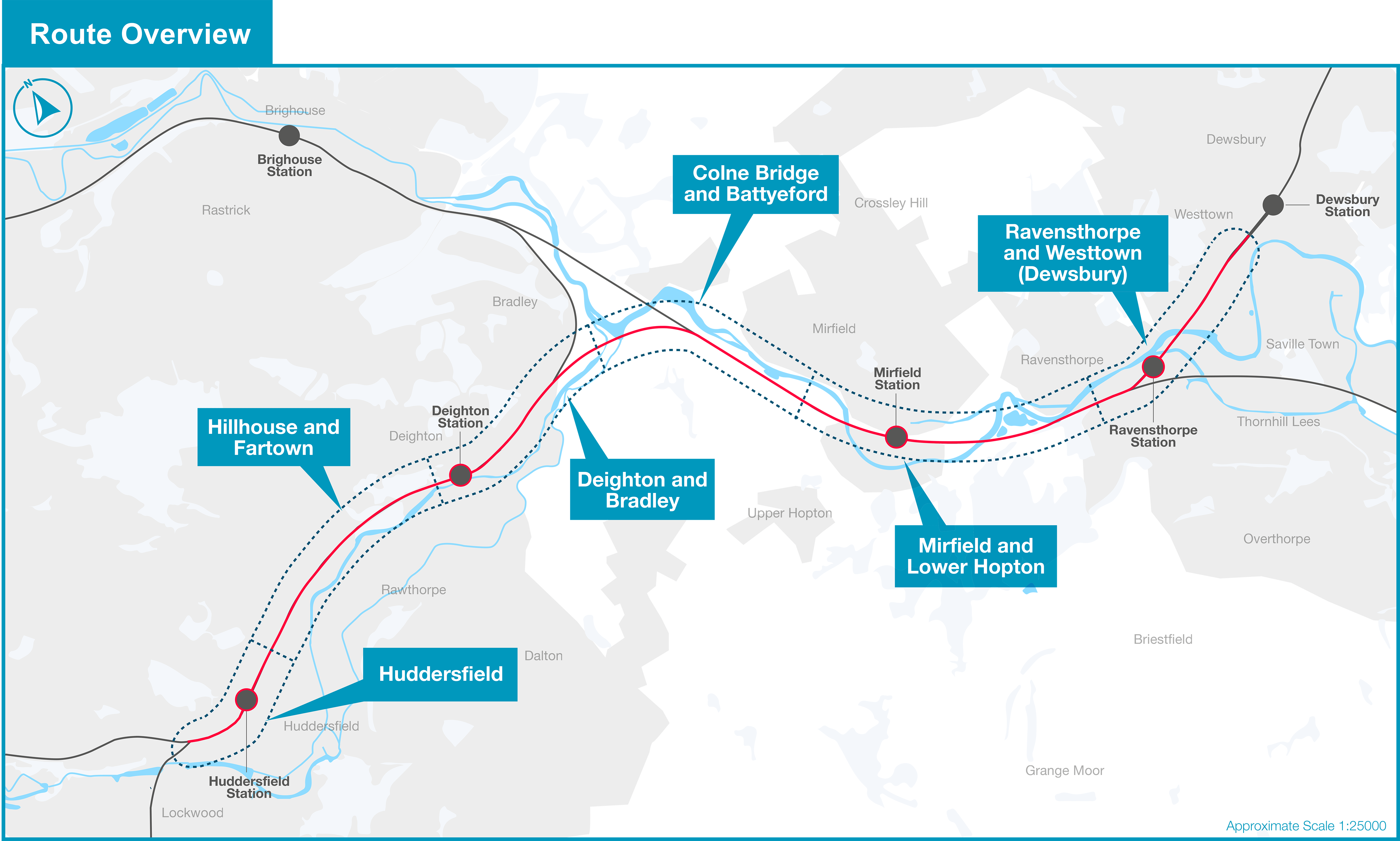
I found a YouTube channel with four driver training videos for the current resignalling between Ravensthorpe and Cottingley. Also shows new speed limits and station upgrades.
The prefix indicates the control area (usually) so Stalybridge to Leeds is a good guess.Does anybody know the logic behind the signal numbers - eg SL 4871?
Is there a route code in the number somewhere, or a location reference?
I'm presuming the SL prefix means StStalybridge-Leeds.
SL could of course be Standedge - Leeds.Impressive video.
Still a number of arched masonry bridges to worry about for the wiring project.
Does anybody know the logic behind the signal numbers - eg SL 4871?
Is there a route code in the number somewhere, or a location reference?
I'm presuming the SL prefix means Stalybridge-Leeds.
I think (but I'm not certain) the S stands for Stalybridge- AIUI that's the boundary between the workstations (one in York ROC, the other in Manchester).SL could of course be Standedge - Leeds.
Related to this, I travelled on the route via Standedge yesterday (and will do so again tomorrow); new precast concrete signal bases are popping up at various points lineside between Hudds and Diggle, so including Standedge Tunnel in its entirety. New hardstanding areas for Location Cabinets (LOCs) are being built along this stretch too, as well as between Ravensthorpe and Leeds.
Good video, that. Surprised that the new bridge at Batley is where it's depicted though (assuming the CGI is accurate), almost on the footprint of the current subway. I'd have thought it'd be closer to the Leeds end of the station, as building the foundations for the steps on top of where the current steps to the footbridge are would presumably be trickier to build. Though disclaimer, I'm no structural engineer.I found a YouTube channel with four driver training videos for the current resignalling between Ravensthorpe and Cottingley. Also shows new speed limits and station upgrades.
")
Yes that is me taking a lot of photo's around Dewsbury, Ravensthorpe & Mirfield, As it was and as it changes, they we can look back in future., While the line was shut last Sunday, I went to Mirfield station, engineers train being loaded with old ballast from where the old 4th track used to be in the past, then they put a membrane down and covered with new ballast. I asked when they where doing more, guy said not till week 40, plus laying new track a xmas he said. We'll see eh. Work on new bridge at Ravensthorpe near years end too. Oh forgot to say, they are boring test holes to check the ground state, where the line crossed the River Calder at Dewsbury, heading towards Ravensthorpe. Told its going to be called Baker Viaduct, crossing river & canal there, beside the old cast iron girder bridge.https://www.flickr.com/photos/rob_transpennine_upgrade/ and https://www.flickr.com/groups/14856999@N21/pool/ are good indicators of work going on between Hudds and Dewsbury.
The former Tilcon sidings at Dewsbury (w3w: https://w3w.co/silent.bunny.update) have been turned into a arrival/departure base for goods by rail for use on TRU W3.
"Mirfield Shed Bridge" (aka MVN2-191 "Woodend Road Overbridge", near Lower Hopton Football Ground) has also been demolished.
Still think the arrangement of the fast/slow down lines at Huddersfield is a mistake. Hopefully common sense will prevail and it'll go back to the original plan.Just to marry up to Stibz photos and descriptions here's what I have saved as the final layout.
View attachment 138674
Presumably there wasn't space for a support between the running lines and sidings without compromising the loading gauge on one or both?One massive long portal, over both Huddersfield lines and the full width of the Sidings on the Up Side at Guide Bridge. That one is strange, I very much doubt the Sidings will be wired.
I take it the 2 Sundays in August 6th and 13th is when they'll finish doing the rest of the wires and gantries?Quite stunning progress with OLE equipment Stalybridge to Guide Bridge. I'd estimate 80% installed, including the Portals seemingly running the full length of Dukinfield viaduct(s). One portal is erected over Ashton Viaduct.
One full wire run on both lines from just after Stalybridge West Jn in place and terminates just before Ashton Viaduct.
OLE structures over the Glossop lines at Guide Bridge West Jn, ready to take over supporting the wires.
One massive long portal, over both Huddersfield lines and the full width of the Sidings on the Up Side at Guide Bridge. That one is strange, I very much doubt the Sidings will be wired.

 thetrupgrade.co.uk
Sorry remind me, what was the original plan? I also look at the Huddersfield layout and don't quite get the logic.Still think the arrangement of the fast/slow down lines at Huddersfield is a mistake. Hopefully common sense will prevail and it'll go back to the original plan.
Presumably there wasn't space for a support between the running lines and sidings without compromising the loading gauge on one or both?
Given they have Transport & Works Act approval, I think that’s highly unlikely.Still think the arrangement of the fast/slow down lines at Huddersfield is a mistake. Hopefully common sense will prevail and it'll go back to the original plan.
Why? Given the need for slow trains to cross with fast eastbound trains, doing it in a platform seems a sensible choice. What am I missing?Still think the arrangement of the fast/slow down lines at Huddersfield is a mistake. Hopefully common sense will prevail and it'll go back to the original plan.
I'm not sure whether the exact positioning of crossovers within works land is required to comply with the exact plans approved.Given they have Transport & Works Act approval, I think that’s highly unlikely.
Originally the lines currently serving platforms 1 & 4 (which will become 2 & 3) were to be the fast lines, meaning the through lines in the station would be paired by use as they will be heading towards Leeds. The current plan is for the new platform 4 (currently 8) to be the Down Fast.Sorry remind me, what was the original plan? I also look at the Huddersfield layout and don't quite get the logic.
I assume what is now P4 is purely for Manchester stoppers? And the new island platform will handle all slow line trains terminating from Deighton direction.
If the diagram posted above is correct, no changes would be required to switch the use of the two through platforms on the middle island. The current plan means every Down fast service has to cross the throat of platform 3, a conflict that doesn't need to happen if the fast lines are kept to the pair of lines closest to the main building.Given they have Transport & Works Act approval, I think that’s highly unlikely.
They only need to cross because of the way the platforms are planned to be used. If the two platforms nearest the main building were the fast lines, no crossing would be necessary.Why? Given the need for slow trains to cross with fast eastbound trains, doing it in a platform seems a sensible choice. What am I missing?
So how do westbound trains get from the westbound slow line east of Huddersfield to the westbound line without crossing the eastbound line?They only need to cross because of the way the platforms are planned to be used. If the two platforms nearest the main building were the fast lines, no crossing would be necessary.
A westbound slow train arriving from the east (I think that's what you're getting at) would simply continue into one of the slow line platforms. If going into the new bay, it would have to cross the eastbound slow but wouldn't need to interact with the fast lines at all. If continuing west of Huddersfield the crossing would happen west of the station, but as the layout will (eventually) reduce from 4 tracks to 3 there anyway, some conflicting moves will be unavoidable. The layout as proposed introduces a conflict that doesn't need to be there.So how do westbound trains get from the westbound slow line east of Huddersfield to the westbound line without crossing the eastbound line?
Still nothing confirmed, but it's widely anticipated that the Manchester stopper is continuing through Huddersfield and working to York via Castleford.I assume what is now P4 is purely for Manchester stoppers? And the new island platform will handle all slow line trains terminating from Deighton direction.
But doing it this way a slow westbound train continuing towards Manchester crosses onto the westbound line in two stages, rather than one if the crossing was west of Huddersfield. So there should be less conflict, not moreA westbound slow train arriving from the east (I think that's what you're getting at) would simply continue into one of the slow line platforms. If going into the new bay, it would have to cross the eastbound slow but wouldn't need to interact with the fast lines at all. If continuing west of Huddersfield the crossing would happen west of the station, but as the layout will (eventually) reduce from 4 tracks to 3 there anyway, some conflicting moves will be unavoidable. The layout as proposed introduces a conflict that doesn't need to be there.
With the layout as proposed, every single slow line arrival into P3 from the Deighton direction will have to cross over the eastbound fast line, and every single fast line departure towards Leeds will have to cross the slow line into platform 3.
East of Huddersfield the slows will be to the north of the formation, so they should use the platforms on that side too. In that case, there would be no interaction between the fasts and slows East of the station in normal operation.
Ah, that does make some sense- two smaller, more manageable conflicts rather than one big one. I was working on the assumption that the plan for the Manchester stopper to run through to Wakefield and beyond was a temporary measure during the upgrade rather than a long-term one. Thus most stoppers would be turning back once the upgrade work was complete.But doing it this way a slow westbound train continuing towards Manchester crosses onto the westbound line in two stages, rather than one if the crossing was west of Huddersfield. So there should be less conflict, not more
I did see all the plans in pdf, sadly I never downloaded them, can't find them now. But I remember a flyover at Ravensthorpe station mentioned in the plans, looks like that is on the drawing above.Just to marry up to Stibz photos and descriptions here's what I have saved as the final layout.
View attachment 138674
It's certainly something that is being looked at and evaluated given that the TransPennine Route upgrade's scope includes improvements for freight flows, however, it would be too far into the future to know whether it would happen.Speaking of Huddersfield, how advanced (if at all?) are the proposals for a third track from Huddersfield to Marsden?
Something I've only just noticed on that plan is the "new" Ravensthorpe station being an island platform. I'm surprised by this as it means the slow lines need to be further apart at that point. Does anyone know the thinking behind this, or should we not be putting much stock in a diagrammatic map which isn't to scale?I did see all the plans in pdf, sadly I never downloaded them, can't find them now. But I remember a flyover at Ravensthorpe station mentioned in the plans, looks like that is on the drawing above.
If a Manchester stopper turned back in P4, it would need a path across the Down Fast for departure, that coincided with its path on the Up Fast. By turning back in P3, this timetabling constraint/potential conflict is avoided.Ah, that does make some sense- two smaller, more manageable conflicts rather than one big one. I was working on the assumption that the plan for the Manchester stopper to run through to Wakefield and beyond was a temporary measure during the upgrade rather than a long-term one. Thus most stoppers would be turning back once the upgrade work was complete.
If the current service pattern continues there are no conflicting moves on the new layout, the Manc Pic stopper would terminate in the new P3 and depart back tight behind an express to Manchester causing no conflicting moves, as now.Ah, that does make some sense- two smaller, more manageable conflicts rather than one big one. I was working on the assumption that the plan for the Manchester stopper to run through to Wakefield and beyond was a temporary measure during the upgrade rather than a long-term one. Thus most stoppers would be turning back once the upgrade work was complete.
As far as I can see, all the plans and documents for the Transport and Works Act application are still online. I just searched for "Huddersfield Westtown" and found this:I did see all the plans in pdf, sadly I never downloaded them, can't find them now. But I remember a flyover at Ravensthorpe station mentioned in the plans, looks like that is on the drawing above.
Yeah, I can see the error in my thinking now- I don't travel West of Huddersfield much, so didn't consider the implications at that end of the station, not least because the third track is still further from happening than the changes in the north/easterly direction.If the current service pattern continues there are no conflicting moves on the new layout, the Manc Pic stopper would terminate in the new P3 and depart back tight behind an express to Manchester causing no conflicting moves, as now.
If the plan is to extend the Manc Pic - Huddersfield stopper to Wakefield/York long term or better still relink it to the Hudds - Leeds stopper then you will have a westbound conflict at the east end only. If you have the conflict at the west end then you need to match up having no eastbound trains conflicting with departing tight behind a westbound express which is harder to achieve. As mentioned above doing the crossover in two steps is easier to plan, the stopper can be timed to sit in Hudds P3 to allow for this.
I would imagine the land take in the area is determined by the need for a smooth alignment for the fast lines, together with the fact that the existing/slow lines have a wiggle to the north. There are much larger scale maps still online at the link I posted above.Something I've only just noticed on that plan is the "new" Ravensthorpe station being an island platform. I'm surprised by this as it means the slow lines need to be further apart at that point. Does anyone know the thinking behind this, or should we not be putting much stock in a diagrammatic map which isn't to scale?
